Offline

So I am preparing to crack open my C64-C and modify it for use with Prophet64,  Cynthcart,  and Retroskoi+, and I am just waiting on some parts before I begin.  I have modded Gameboys before,  my Atari too... but never a C64(c),  so I am a little bit nervous.  I've done plenty of kit building and circuit bending though,  so I have the skills needed...  it's just that I would like more documentation on how to do the mods.

These are the mods that I wish to add:

+SID2SID - already bought chip (8580),  pcb,  and parts... (I have the manual for this mod,  so I'm pretty good...)
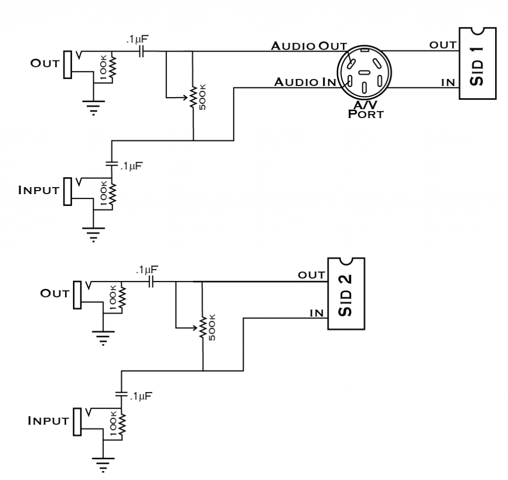
+Audio output(s?)
+Feedback knob - still need to get parts
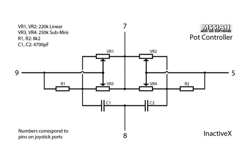
+4 potentiometers with a switch to avoid keyboard conflicts (and still be able to use port 2 for mouse) - still need to get parts
+noise reduction (?) (maybe)
+New led - orange smile


So far,  all I could find online to help me is this link,  from AlphA:

http://www.bigmech.com/misc/c64mods/

Which is great,  but not quite as detailed as I would like it to be...  And he does a lot of mods that I'm not doing...so he's doing things a little differently.

Does anybody know where to find additional information on these specific mods?  Has anyone out there performed any of these mods and has any tips?

I would try the Prophet64/ MSSIAH forums,  but it seems no one really uses those much anymore so I'm trying here... Also,  because this forum is awesome!

Thanks for your help!

Offline
Dallas, Texas

Yes sir. You shoud use this schematic for your potentiometers. Super accurate and no dead zones. Those submini pots are trimmers that you use to fine tune your dead zones away.


Also most of what you need to know has already been discussed in the MSSIAH-FORUM. I would just browse the old threads for what you need to know.

Last edited by TylerBarnes (Sep 20, 2014 4:11 pm)

Offline

Thanks!  Good idea with the trimmers...

I also found this browsing the Mssiah forums,  is it pretty much the same?:

I'd also like to add a switch so that I can still use my 1351 mouse with the Sequencer....but the schematic does not show where that would go...

Edit-  it appears the switch would go between pin 7 and the circuit,  cutting off the power supply to it.

Last edited by RJL (Sep 21, 2014 3:31 am)

Offline
Dallas, Texas

That schematic you have is the simple and easiest way of doing it, but will result in dead zones where the value on screen is maxed out before the pot is fully turned to its limit. Again, it's not too terribly annoying or anything a definitely something that you could get used to. Many of us have accepted the dead zones as they don't impede workflow a great deal. The schematic I posted would have to be built twice for each controller port.

I haven't modded a c64 in quite some time now, but yes the pots, I believe, are wired up like variable voltage dividers. You just need to break power to those with your switch(es).


Also to touch on a few of your other mod quaries:

- Noise reduction with be very tricky on a c64 as most of it comes from the power supply, and then also I think a smidge from the video chip (I forget).

- Feedback pot and Audio outs can be wired like this (it's how mine is currently wired) :

I just tapped into the AV Port (shown in schematic) for SID 1's in and out but you can go direct like SID 2 if you want.

Offline

Thanks! This is all very helpful!

Offline

How are audio inputs used on the c64?

Offline
Dallas, Texas

Use one: Routing external audio through the SID's wonderful filter.
Use two: Routing the SID's own output into itself creating feedback and more filer resonance.

Last edited by TylerBarnes (Sep 21, 2014 1:13 pm)

Offline

Some clarifications,  if you don't mind...  (Thank you for all your help so far)

Does your C64 have 2 feedback knobs then?  It looks like you just turn them down all the way when you don't want any feedback,  and simply turn them up for feedback,  correct?  No switch needed... Or do you have to use a cable to connect the input to the output?

Do you have a switch/ switches for your pots?  I have heard of people using just one switch.... Does that one switch cut power to all 4 pots then?

With the audio outputs wired as such,  I would no longer need the audio output through the av wire,  right?  You just need 2 mono cables going from the new outputs to your mixer.  Does it output to both a/v and new output at the same time?


I noticed your schematic for the pots has caps,  just wondering the purpose of the caps...

Still deciding if I want to go with your schem,   or the easier one for the pots.... hmm


I'm planning on ordering the rest of my parts soon,  so I'm sort of finalizing what I still need to get smile

Offline
Dallas, Texas

Two feedback knobs; One for each SID. You can prolly combine them into one or even use a dual ganged/stereo pot if you prefer less control over each feedback loop. No switch needed, 500k is plenty to prevent feedback from happening until you want it.

I personally use only one switch but it is only disconnecting controller port 2 so I can use a mouse. You can use a DPDT switch if you want to disconnect both pairs of pots with one switch.

The caps are AC coupling caps that block DC voltage.

If you just starting out theres no problem with the simpler mod for the pots. Sure it has the minor dead zone issue but if you feel like that bothers you later down the line you can always change it.

Offline

I was wondering if the combination of resistance and caps smoothed out that jittery-ness that the pots seem to have?

Offline
Dallas, Texas

The ones I made aren't very jittery. That might just be due to the quality of the pots though... this I am unsure about.


I wanted to mention something else about the feedback mod that I just remembers. if you use a pot that has a pushbutton switch you can use it to ground the SID's audio input when you are not using the feedback mod. this will clean up alot of unwanted noise that the SID produces. Ideal for when you want to record pristine SID audio (provided you aren't using feedback in your track)

Offline

I think AlphA used "switching" jacks to do the same thing:

http://www.bigmech.com/misc/c64mods/feedbackloop.html

Offline

Oops ,  wrong link... Here:

http://www.bigmech.com/misc/c64mods/noisereduction.html

Offline

So I decided to go with the schematic that uses the trimpots,  it will just be a lot nicer that way. 

I feel pretty confident now about the mods I'm adding,  so I ordered the rest of the parts that I needed. 

Hopefully next weekend I can get started!

Thanks again!

Offline
Dallas, Texas

Good luck! and post photos when you're done! ;P

My buddy reminded me of something the other day that I thought I'd pass on to you as well. If you are planning on using the SID's inputs for injecting external audio sources like a laptop or CD player, it would be very wise to use a cable that has a Ground Loop Isolator, so the difference in voltage doesn't kill your SID. These can be found at radio shack easily. I use this one for mine. http://www.radioshack.com/product/index … Id=2062214

Last edited by TylerBarnes (Sep 27, 2014 7:36 am)

Offline

So,  do you have RCA jacks on your c64,  or are you using some sort of adapter?

Would I use this ground loop isolator for every signal that I want to input through the C64?  I.e.  Gameboy,  circuit bent Casio,  DIY synths,  etc???