There are already a couple of tutorials about "biversion" i.e. installing an IC to invert the signal going into the LCD so that it outputs inverted (negative). When you combine this with an inverted backlight, the two "inversions" cancel out and the negative display becomes positive again (i.e. normal), but with improved contrast compared to a normal (non-inverted) backlight.
http://mikejmoffitt.com/tut/tut_dmg_bivert.html
http://mikejmoffitt.com/tut/tut_mgb_bivert.html
http://blog.gg8.se/wordpress/2009/11/23 … d-palette/
(BTW For people only using LSDJ, you can get the same effect just by getting an inverted backlight and changing the "LOOK" setting to "INV")
I wanted to do this mod on my DMG but didn't like the idea of a big fat DIP IC showing at the top, so I did it a little neater and thought I'd show people how. Please note: this is just one way of doing the "biversion" mod, which I thought combined easy mounting, minimal wiring and getting it out of the way.
I used a dual inverter IC in a tiny surface-mount package (SOT-23). There are smaller packages for dual inverters, but the SOT-23 size is common enough that I could use an easily available (and cheap) breakout board, instead of making my own custom board. It's also easy to solder manually with a soldering iron and flux.
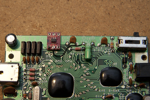
Just like the other examples of "biversion", I'm connecting the inputs of two inverter gates to two pads in the 3x2 group of unused pads, which connect to the output of the CPU. Conveniently, the pads on the breakout board align with the holes on the PCB, so I mounted the board using solid core wire through the DMG's PCB and the breakout board. I first sucked the solder out of those pads using a solder sucker (desoldering pump) on one side while heating the pad/hole from the other. BTW this is the easiest way to suck solder out of any pad, especially plated through-holes, and the holes on the DMG are huge compared to other boards I've had to desolder (including my own designs!), so I should stress to soldering newbies that this is an easier step than it sounds, especially since you don't even need to remove any leads from those holes. I then soldered about 20mm of solid core wire into the desoldered holes using a bit of flux on the pad and carrying a solder blob to the joint. (Newbies: hold the wire with pliers, not fingers!)
The wire to ground was soldered onto the breakout board before soldering the breakout board onto the two solid core wire "pins", this keeps it flat on the bottom side, and ensuring it would not touch or bridge to the pad between the two "input" pads on the DMG's PCB, which might happen if soldered after the breakout board is mounted.
I used a piece of card to keep the breakout board about 0.5mm above the DMG's PCB while soldering the two solid core wire "pins" to the breakout board. Then I soldered the ground wire to the C6 capacitor's negative pin, which is ground.

On the other side of the PCB, I cut the tracks leading away from the two pins on the ribbon cable connnector, the same way as the other "biversion" tutorials. (Newbies: this step is not optional). It's important to cut between the connector pin and the via (where shown in the photo). The other cut track is obscured by the wire in this photo, it's the same "cut", just to the left. I soldered wires between the inverter gate outputs on the breakout board and the pins on the ribbon cable connector. Again, this is easiest done with a bit of flux and carrying a solder blob to the pin. I soldered another wire between the middle pin on that side of the breakout board and the nearest pin on 5V.
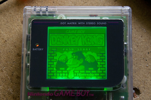
And now the money shot: something that isn't LSDJ showing gloriously high contrast biverted backlit LCD.
Parts Used (aka. boring technical details)
Super Awesome LEDx3 Backlight (vb/inverted) from kitsch-bent: http://store.kitsch-bent.com/product/ledx3
SOT23 to DIP Adapter (breakout board) from SparkFun: http://www.sparkfun.com/products/717
Dual Inverter Gate in SOT23 package, eg. SN74LVC2GU04DBVR (Mouser Part # 595-SN74LVC2GU04DBVR)
CHIP QUIK® Tack Flux - 2cc Squeeze Tube: http://chipquik.com/store/prod_smd291st2cc6.htm
Thick solid core wire (like what you use in breadboards)
Wire Wrapping Wire (30 AWG solid core, Kynar Insulation) (eg. Mouser Part # 801-R30BLK)
Questions and feedback welcome.
Higher res photos on Flickr
BTW, I'll be doing the same thing to my Gameboy Pocket, after I get more backlights from kitsch ![]()