<?xml version="1.0" encoding="utf-8"?>
<feed xmlns="http://www.w3.org/2005/Atom">
	<title type="html"><![CDATA[ChipMusic.org - C64 Pot Controller - New Circuit]]></title>
	<link rel="self" href="https://chipmusic.org:80/forums/feed/atom/topic/4630/"/>
	<updated>2019-12-10T20:30:57Z</updated>
	<generator>PunBB</generator>
	<id>https://chipmusic.org/forums/topic/4630/c64-pot-controller-new-circuit/</id>
		<entry>
			<title type="html"><![CDATA[Re: C64 Pot Controller - New Circuit]]></title>
			<link rel="alternate" href="https://chipmusic.org/forums/post/262781/#p262781"/>
			<content type="html"><![CDATA[<p>R1 and R2 are 8k2.</p><p>Theres a tiny bit more info to pick thru here:<br /><a href="http://www.mssiah-forum.com/viewtopic.php?id=1935" target="_blank">http://www.mssiah-forum.com/viewtopic.php?id=1935</a></p><div class="quotebox"><cite>http://www.mssiah-forum.com/viewtopic.php?pid=15146#p15146 wrote:</cite><blockquote><p>You have a certain lee-way with the values of the pots and caps. The important one to get right on is R1 and R2 (8k2). This affects the taper of the pots, and 8k2 is the ideal fit, regardless of what the other components are rated at.</p><p>The 100k pots are a little on the low side though. If you get some higher R ones that might be better (you may find that the trims&#039; sweet spot is near the edge of the dial the way you have it now).</p></blockquote></div><p>This was in response to someone asking if 2200pF caps were ok to use. The caps reduce jitter, but too high and you&#039;ll have delayed response of the knobs.</p>]]></content>
			<author>
				<name><![CDATA[Orgia Mode]]></name>
				<uri>https://chipmusic.org/Orgia+Mode</uri>
			</author>
			<updated>2019-12-10T20:30:57Z</updated>
			<id>https://chipmusic.org/forums/post/262781/#p262781</id>
		</entry>
		<entry>
			<title type="html"><![CDATA[Re: C64 Pot Controller - New Circuit]]></title>
			<link rel="alternate" href="https://chipmusic.org/forums/post/262780/#p262780"/>
			<content type="html"><![CDATA[<p>As far as I can see it&#039;s:</p><p>VR1, VR2 220K <br />VR3, VR4 (trimmers) 250K Sub-mini <br /><strong><em>R1, R2 ?K2</em></strong> <br />C1, C2 4700pF </p><p>What are R1 and R2? </p><p>and have I got the others correct? The image is tiny!</p><p>This is the clearest I can find:</p><p><a href="http://www.bugcompass.co.uk/c64/IMG_2004.png" target="_blank">diagram</a></p><p>Thanks</p>]]></content>
			<author>
				<name><![CDATA[neonlike]]></name>
				<uri>https://chipmusic.org/neonlike</uri>
			</author>
			<updated>2019-12-10T20:18:04Z</updated>
			<id>https://chipmusic.org/forums/post/262780/#p262780</id>
		</entry>
		<entry>
			<title type="html"><![CDATA[Re: C64 Pot Controller - New Circuit]]></title>
			<link rel="alternate" href="https://chipmusic.org/forums/post/262777/#p262777"/>
			<content type="html"><![CDATA[<p>Thanks. I have read through but the values are not present and seem to conflict with what I can make out from the best version of this image I can find. </p><p>There’s one in google images but the values aren’t clear. </p><p>The maplin codes don’t exist anymore and they replied to me saying they no longer stock those parts.</p>]]></content>
			<author>
				<name><![CDATA[neonlike]]></name>
				<uri>https://chipmusic.org/neonlike</uri>
			</author>
			<updated>2019-12-09T10:35:15Z</updated>
			<id>https://chipmusic.org/forums/post/262777/#p262777</id>
		</entry>
		<entry>
			<title type="html"><![CDATA[Re: C64 Pot Controller - New Circuit]]></title>
			<link rel="alternate" href="https://chipmusic.org/forums/post/262775/#p262775"/>
			<content type="html"><![CDATA[<div class="quotebox"><cite>neonlike wrote:</cite><blockquote><p>Sorry to bump an old post...</p><p>Is this the diagram in the OP&#039;s post?</p><p><a class="postimg" href="https://i77.photobucket.com/albums/j43/frightendghoul/mssiah_pots.jpg" title="https://i77.photobucket.com/albums/j43/frightendghoul/mssiah_pots.jpg" id="forum_image_10536750"><img src="https://i77.photobucket.com/albums/j43/frightendghoul/mssiah_pots.jpg" /></a></p><p>Does anyone have a clear image of the diagram and a correct list of components (including values)?</p><p>Thank you</p></blockquote></div><p>Check page 2 of the thread. Several people made different visualization of the schematic.</p>]]></content>
			<author>
				<name><![CDATA[Orgia Mode]]></name>
				<uri>https://chipmusic.org/Orgia+Mode</uri>
			</author>
			<updated>2019-12-08T21:08:01Z</updated>
			<id>https://chipmusic.org/forums/post/262775/#p262775</id>
		</entry>
		<entry>
			<title type="html"><![CDATA[Re: C64 Pot Controller - New Circuit]]></title>
			<link rel="alternate" href="https://chipmusic.org/forums/post/262774/#p262774"/>
			<content type="html"><![CDATA[<div class="quotebox"><cite>akira^8GB wrote:</cite><blockquote><p>Well it&#039;s me again.<br />I am trying to get the parts and I am having problems sourcing electrolytic 4700pF capacitors. Can I use ceramic ones, the ones shaped as little discs? I read somewhere they might introduce noise to analog signals so they might not be the best thing to use...</p></blockquote></div><p>I try not use ceramic within the audio signal on boards I sell, but if its an analog envelope or lfo, or decoupling then its fair game. The &quot;noise&quot; it introduces is actually quite trivial.<br />I would recommend film caps for smaller values. <br /><a href="https://www.taydaelectronics.com/4-7nf-0-0047uf-100v-5-polyester-film-box-type-capacitor.html" target="_blank">https://www.taydaelectronics.com/4-7nf- &#133; citor.html</a></p><p>Also note that 4700 pico = 4.7 nano = 0.0047 micro.</p><p>EDIT: nice, I thought the new post wa on page 1. <img src="https://chipmusic.org/forums/img/smilies/tongue.png" width="15" height="15" alt="tongue" /> Nevermind me...</p>]]></content>
			<author>
				<name><![CDATA[Orgia Mode]]></name>
				<uri>https://chipmusic.org/Orgia+Mode</uri>
			</author>
			<updated>2019-12-08T20:27:04Z</updated>
			<id>https://chipmusic.org/forums/post/262774/#p262774</id>
		</entry>
		<entry>
			<title type="html"><![CDATA[Re: C64 Pot Controller - New Circuit]]></title>
			<link rel="alternate" href="https://chipmusic.org/forums/post/262773/#p262773"/>
			<content type="html"><![CDATA[<p>Sorry to bump an old post...</p><p>Is this the diagram in the OP&#039;s post?</p><p><a class="postimg" href="https://i77.photobucket.com/albums/j43/frightendghoul/mssiah_pots.jpg" title="https://i77.photobucket.com/albums/j43/frightendghoul/mssiah_pots.jpg" id="forum_image_15970006"><img src="https://i77.photobucket.com/albums/j43/frightendghoul/mssiah_pots.jpg" /></a></p><p>Does anyone have a clear image of the diagram and a correct list of components (including values)?</p><p>Thank you</p>]]></content>
			<author>
				<name><![CDATA[neonlike]]></name>
				<uri>https://chipmusic.org/neonlike</uri>
			</author>
			<updated>2019-12-08T17:16:12Z</updated>
			<id>https://chipmusic.org/forums/post/262773/#p262773</id>
		</entry>
		<entry>
			<title type="html"><![CDATA[Re: C64 Pot Controller - New Circuit]]></title>
			<link rel="alternate" href="https://chipmusic.org/forums/post/174432/#p174432"/>
			<content type="html"><![CDATA[<p>I fixed it! I had ground and 5v swapped by mistake. I feel stupid.</p><p>In the end I went with a 4PDT switch that reroutes the data lines for both ports (1X/1Y/2X/2Y), and I connected the power and ground lines for all 4 potentiometers straight to port 1&#039;s pins on the underside of the motherboard. When the ports are switched on, my mouse works in port 2. I haven&#039;t tried using an external controller in port 1 yet.</p>]]></content>
			<author>
				<name><![CDATA[Awol]]></name>
				<uri>https://chipmusic.org/Awol</uri>
			</author>
			<updated>2013-06-27T00:16:41Z</updated>
			<id>https://chipmusic.org/forums/post/174432/#p174432</id>
		</entry>
		<entry>
			<title type="html"><![CDATA[Re: C64 Pot Controller - New Circuit]]></title>
			<link rel="alternate" href="https://chipmusic.org/forums/post/174406/#p174406"/>
			<content type="html"><![CDATA[<p>Well I tried the switch method suggested by nitro and now my mouse works but the pots don&#039;t anymore! I&#039;ll have to double check all the connections and see if there&#039;s a short circuit somewhere or something.</p><p>At least the JiffyDOS and uIEC/SD that I just put in work fine. I even managed to desolder the original kernel without damaging it... Ok, I broke one leg.</p><div class="quotebox"><cite>akira^8GB wrote:</cite><blockquote><p>Well the silliest thing he has done is the case shrinking mod <img src="https://chipmusic.org/forums/img/smilies/big_smile.png" width="15" height="15" alt="big_smile" /> but for example his &quot;noise reduction&quot; mod just doesn&#039;t work.</p></blockquote></div><p>I do get significantly less noise with Alpha&#039;s noise reduction mod. Perhaps it&#039;s less effective on certain motherboard or SID revisions? I&#039;ve got a C64C with 8580 SIDs.</p>]]></content>
			<author>
				<name><![CDATA[Awol]]></name>
				<uri>https://chipmusic.org/Awol</uri>
			</author>
			<updated>2013-06-26T21:14:02Z</updated>
			<id>https://chipmusic.org/forums/post/174406/#p174406</id>
		</entry>
		<entry>
			<title type="html"><![CDATA[Re: C64 Pot Controller - New Circuit]]></title>
			<link rel="alternate" href="https://chipmusic.org/forums/post/172941/#p172941"/>
			<content type="html"><![CDATA[<div class="quotebox"><cite>Awol wrote:</cite><blockquote><p>Thanks for posting the schematic! The perfectionist side of me was considering re-doing my pots InactiveX style, but I&#039;m too lazy, and now you say it&#039;s not worth it. I don&#039;t think I&#039;ll use the pots much anyway. Expect I&#039;ll spend most of my time checking out SID Wizard once I get my uIEC/SD connected internally.</p></blockquote></div><p>
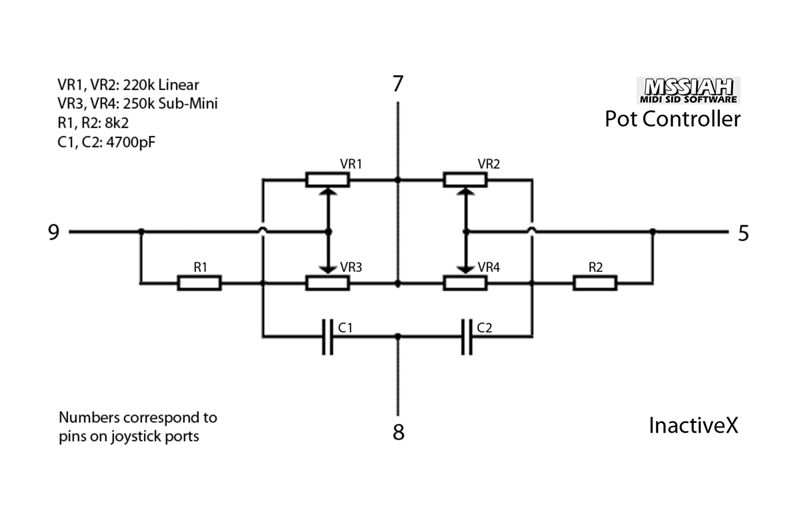
One of the pots still had tapering and even though the other one seemed to be working fine, it was still imprecise to get to a sweet spot for the range. Personally, I didn&#039;t think it was that necessary specially if you have MSSIAH and can connect a proper MIDI controller to it. Then you don&#039;t have to deal with finicky, flickery C64 pots. I mean, the computer looks bad ass, and it&#039;s convenient to have them in-built without depending on an external control surface, but although having them go full range by mid-turn of a pot is annoying, building this circuit was a lot more effort for me and the end result was only marginally better. I still got to try using diffrently rated potentiometers. Haven&#039;t been able to bag a C64 I can restore and sell.</p><div class="quotebox"><cite>Awol wrote:</cite><blockquote><p>Wouldn&#039;t cutting X and Y disconnect the pots as effectively as cutting GND or 5V? What could go wrong if you leave the pots powered but with their data output disconnected like nitro said?</p></blockquote></div><p>As I said I know nothing about electronics, but I am also quite cautious when dealing with it. The potentiometers connect to the SID and you don&#039;t want to screw up your SID.</p><p>So if you disable the data lines and connect a mouse, you are still giving voltage to the mouse AND the pots. Although no data is sent, I rather NOT have two devices plugged in to one port&#039;s voltage bits at the same time as the ports were not designed for that. <br />What I say may not make any sense if you know electronics, but I rather be safe. The effect is the same after all. <br />The main difference I see here is that if you cut the data lines instead of the power, you may be able to switch it on or off while the machine is on, while my switch is only to be operated with the machine off to be totally safe. My switch is also easier, less cables to mess with.</p><div class="quotebox"><cite>Awol wrote:</cite><blockquote><p>Hm. Why, what else did he do that seems silly?</p></blockquote></div><p>Well the silliest thing he has done is the case shrinking mod <img src="https://chipmusic.org/forums/img/smilies/big_smile.png" width="15" height="15" alt="big_smile" /> but for example his &quot;noise reduction&quot; mod just doesn&#039;t work. Doing it properly requires a lot more work. If you are interested in a full bad-ass noise reduction mod, check out Vandalism News #58&#039;s Hardware Corner section where Lemming explains a proper one, but it&#039;s not for the faint of heart. I didn&#039;t dare make it: <a href="http://csdb.dk/release/?id=102732" target="_blank">http://csdb.dk/release/?id=102732</a></p>]]></content>
			<author>
				<name><![CDATA[akira^8GB]]></name>
				<uri>https://chipmusic.org/akira%5E8GB</uri>
			</author>
			<updated>2013-06-16T15:39:20Z</updated>
			<id>https://chipmusic.org/forums/post/172941/#p172941</id>
		</entry>
		<entry>
			<title type="html"><![CDATA[Re: C64 Pot Controller - New Circuit]]></title>
			<link rel="alternate" href="https://chipmusic.org/forums/post/172777/#p172777"/>
			<content type="html"><![CDATA[<div class="quotebox"><cite>akira^8GB wrote:</cite><blockquote><p>This is my idiot-proof schematic, for people that have no idea of electronics (like me) and want to build two pots with disable switch for port 2 potentiometers:</p><p>I have to say I built this and really didn&#039;t think it was necessary to bother. I think different rate potentiometers might yield similar results.</p></blockquote></div><p>Thanks for posting the schematic! The perfectionist side of me was considering re-doing my pots InactiveX style, but I&#039;m too lazy, and now you say it&#039;s not worth it. I don&#039;t think I&#039;ll use the pots much anyway. Expect I&#039;ll spend most of my time checking out SID Wizard once I get my uIEC/SD connected internally.</p><div class="quotebox"><cite>akira^8GB wrote:</cite><blockquote><p>The way I do the switch is by connecting the power lines of the pots of the same port together then onto the +5 lne, so all I have is to connect that line to a single switch. You don&#039;t need a DPDT switch. No power, no pot. Mouse works fine. I wouldn&#039;t like to power the mouse and the pots at the same time on the same pot, sounds prone to disaster.</p></blockquote></div><p>Wouldn&#039;t cutting X and Y disconnect the pots as effectively as cutting GND or 5V? What could go wrong if you leave the pots powered but with their data output disconnected like nitro said? </p><div class="quotebox"><cite>akira^8GB wrote:</cite><blockquote><p>As a side note, I wouldn&#039;t do almost ANYTHING that Alpha recommends.</p></blockquote></div><p>Hm. Why, what else did he do that seems silly?</p>]]></content>
			<author>
				<name><![CDATA[Awol]]></name>
				<uri>https://chipmusic.org/Awol</uri>
			</author>
			<updated>2013-06-15T03:47:22Z</updated>
			<id>https://chipmusic.org/forums/post/172777/#p172777</id>
		</entry>
		<entry>
			<title type="html"><![CDATA[Re: C64 Pot Controller - New Circuit]]></title>
			<link rel="alternate" href="https://chipmusic.org/forums/post/172536/#p172536"/>
			<content type="html"><![CDATA[<p>This is my idiot-proof schematic, for people that have no idea of electronics (like me) and want to build two pots with disable switch for port 2 potentiometers:</p><p><a class="postimg" href="http://i.imgur.com/yh7I4xH.png" title="http://i.imgur.com/yh7I4xH.png" id="forum_image_92897592"><img src="http://i.imgur.com/yh7I4xH.png" /></a></p><p>Just connect things together this way and you are good to go.<br />The components I used are the ones described by InactiveX in the first post of the thread.<br />The way I do the switch is by connecting the power lines of the pots of the same port together then onto the +5 lne, so all I have is to connect that line to a single switch. You don&#039;t need a DPDT switch. No power, no pot. Mouse works fine. I wouldn&#039;t like to power the mouse and the pots at the same time on the same pot, sounds prone to disaster.</p><p>As a side note, I wouldn&#039;t do almost ANYTHING that Alpha recommends.</p><p>I have to say I built this and really didn&#039;t think it was necessary to bother. I think different rate potentiometers might yield similar results.</p>]]></content>
			<author>
				<name><![CDATA[akira^8GB]]></name>
				<uri>https://chipmusic.org/akira%5E8GB</uri>
			</author>
			<updated>2013-06-13T21:37:12Z</updated>
			<id>https://chipmusic.org/forums/post/172536/#p172536</id>
		</entry>
		<entry>
			<title type="html"><![CDATA[Re: C64 Pot Controller - New Circuit]]></title>
			<link rel="alternate" href="https://chipmusic.org/forums/post/172523/#p172523"/>
			<content type="html"><![CDATA[<p>Wow, thanks a lot!</p><p>I&#039;ll do the last option, but instead of a DPDT per port, I&#039;ll use the 4PDT I already have to switch all 4 pots on/off at once. One less hole to drill in the case I just spraypainted.</p>]]></content>
			<author>
				<name><![CDATA[Awol]]></name>
				<uri>https://chipmusic.org/Awol</uri>
			</author>
			<updated>2013-06-13T19:01:31Z</updated>
			<id>https://chipmusic.org/forums/post/172523/#p172523</id>
		</entry>
		<entry>
			<title type="html"><![CDATA[Re: C64 Pot Controller - New Circuit]]></title>
			<link rel="alternate" href="https://chipmusic.org/forums/post/172462/#p172462"/>
			<content type="html"><![CDATA[<p>Switching 5 and 9 (the analog inputs) should be enough. You don&#039;t really need to put a switch on 7 and 8 (+5V and ground). Using a 4PDT switch is way overkill. </p><p>Now, there are different degrees of cheapness you could aim for. Here are a couple of modified schematics with descriptions. I&#039;ve marked +5V with red and ground with black for clarity.</p><p><a class="postimg" href="http://i.imgur.com/G4dixT6.png" title="http://i.imgur.com/G4dixT6.png" id="forum_image_12153540"><img src="http://i.imgur.com/G4dixT6.png" /></a> <strong>Terribly cheap:</strong> Two SPST switches. Connect 5 and 9 right through to the other jack, and connect the potentiometers in parallel through individual SPST switches. Now both switches must be in the on position for the respective potentiometer to work, and both switches must be off in order for the second jack to work properly.</p><p><a class="postimg" href="http://i.imgur.com/XRHiGOD.png" title="http://i.imgur.com/XRHiGOD.png" id="forum_image_30991281"><img src="http://i.imgur.com/XRHiGOD.png" /></a> <strong>Still terribly cheap:</strong> Two SPDT switches. Each input is now properly switched between the potentiometer and the second jack, but you still have two switches you need to care about.</p><p><a class="postimg" href="http://i.imgur.com/zFzOEqq.png" title="http://i.imgur.com/zFzOEqq.png" id="forum_image_79178903"><img src="http://i.imgur.com/zFzOEqq.png" /></a> <strong>Somewhat less cheap:</strong> One DPST switch. Same as the first example, but with only one switch to care about.</p><p><a class="postimg" href="http://i.imgur.com/DFKgxTJ.png" title="http://i.imgur.com/DFKgxTJ.png" id="forum_image_86064302"><img src="http://i.imgur.com/DFKgxTJ.png" /></a> <strong>Recommended:</strong> One DPDT switches. Both lines are properly switched with a single stroke.</p>]]></content>
			<author>
				<name><![CDATA[nitro2k01]]></name>
				<uri>https://chipmusic.org/nitro2k01</uri>
			</author>
			<updated>2013-06-13T10:05:47Z</updated>
			<id>https://chipmusic.org/forums/post/172462/#p172462</id>
		</entry>
		<entry>
			<title type="html"><![CDATA[Re: C64 Pot Controller - New Circuit]]></title>
			<link rel="alternate" href="https://chipmusic.org/forums/post/172439/#p172439"/>
			<content type="html"><![CDATA[<div class="quotebox"><cite>Timbob wrote:</cite><blockquote><p>If i wanted to make this circuit easy to turn on and off while being internally build (so i can also use other joysticks)<br />Which connections should I disconnect? all four?</p></blockquote></div><div class="quotebox"><cite>InactiveX wrote:</cite><blockquote><p>OK. A simple SPST switch to break either line 7 or 8 should do the job then.</p></blockquote></div><p><strong>Is it really that easy? Why does <a href="http://www.bigmech.com/misc/c64mods/ctrlport2.html" target="_blank">this site</a> use such a complicated switch then?:</strong><br /><a class="postimg" href="http://www.bigmech.com/misc/c64mods/ctrlport2potswitchingcircuit.gif" title="http://www.bigmech.com/misc/c64mods/ctrlport2potswitchingcircuit.gif" id="forum_image_89716601"><img src="http://www.bigmech.com/misc/c64mods/ctrlport2potswitchingcircuit.gif" /></a></p><p>That&#039;s 4PDT right? And their schematic also doesn&#039;t account for the other 2 pots, if you&#039;re using 2 per port (4 total).</p><p>I installed 4 internal pots in my C64C a few years ago and miraculously they seem to work smoothly although they don&#039;t use the full rotation (haven&#039;t tried InactiveX&#039;s new method). However, I did something wrong when I added the switch that supposedly disables them! Now my mouse won&#039;t work. The pots still do when I have the switch set to turn them on. The way I currently have it wired, my switch redirects 5v and GND on all 4 pots, as well as X and Y on Port 2. So why is my mouse buggy?</p><p>I spent today trying to figure out the mess of wires I soldered a few years ago. Would be great if someone could answer my questions above. Thanks!</p>]]></content>
			<author>
				<name><![CDATA[Awol]]></name>
				<uri>https://chipmusic.org/Awol</uri>
			</author>
			<updated>2013-06-13T06:21:35Z</updated>
			<id>https://chipmusic.org/forums/post/172439/#p172439</id>
		</entry>
		<entry>
			<title type="html"><![CDATA[Re: C64 Pot Controller - New Circuit]]></title>
			<link rel="alternate" href="https://chipmusic.org/forums/post/170454/#p170454"/>
			<content type="html"><![CDATA[<p>i tried this when I first saw it on the mssiah forum. works a treat!</p>]]></content>
			<author>
				<name><![CDATA[handbaked]]></name>
				<uri>https://chipmusic.org/handbaked</uri>
			</author>
			<updated>2013-06-01T23:59:13Z</updated>
			<id>https://chipmusic.org/forums/post/170454/#p170454</id>
		</entry>
</feed>
