Offline
Boddah wrote:

Here's a tool that I would highly suggest looking into if you don't already have something similar,
http://www.radioshack.com/product/index … Id=3928375

Get a 'helping hands' from Harbor Freight.  It's $6 and the magnifying glass has an LED built in and it comes with batteries.  Can't beat that.  RadioShack sucks.  Haha

Offline
Austin, TX

GoingHam-
I'm going to check that out, I believe your first suggestion could be the solution. I think I cut the corner down a bit to much and damaged the big trace down to the two bottom yellow points in your pic. I checked the row of four points near the top and those are all connected. After checking that I'll go ahead and reinforce the power board's connections and test it out. Thank you so much for your help, I'll be sure to let you know how it works out very soon!
And yes, there will be a big update in the coming days...

nerdsome-
I'll be sure to look into that, thanks!

Offline
Austin, TX

Alright so I checked the connections for the points in your pic, GoingHam. All of the yellow points are indeed still connected to the purple point. I also reinforced the connections to the power board, but I'm still getting the same thing....
I'm thinking the problem may be caused by the power switch. When removing the power switch and adding a new one, wouldn't you just need to connect the pins in the correct order on the switch? Would cutting down that corner cause any problems? I'm almost certain that I only cut the ground pad off of the top left corner so I can't figure out what would be causing the problem...
I think what I'll do is remove all of the parts (power board/switch, cap C1), remove all of the old caps, clean the board thoroughly, put the new caps in, and reconnect all of the parts then see if that helps. If anyone has any other suggestions please shoot them my way!
Offline
Chicago
Boddah wrote:

Alright so I checked the connections for the points in your pic, GoingHam. All of the yellow points are indeed still connected to the purple point. I also reinforced the connections to the power board, but I'm still getting the same thing....
I'm thinking the problem may be caused by the power switch. When removing the power switch and adding a new one, wouldn't you just need to connect the pins in the correct order on the switch? Would cutting down that corner cause any problems? I'm almost certain that I only cut the ground pad off of the top left corner so I can't figure out what would be causing the problem...
I think what I'll do is remove all of the parts (power board/switch, cap C1), remove all of the old caps, clean the board thoroughly, put the new caps in, and reconnect all of the parts then see if that helps. If anyone has any other suggestions please shoot them my way!

The switch should work when connected to correct order of pins. Cutting the board shouldn't be to much of a problem, you could try tracing back the leads to those 4 points for the power switch. I'd say reconfirm your presumed pin out of the stock power switch by using your multimeter on a currently working PCB. Its worth checking if attaching the old switch fixes it as that rules everything else out. Although the one horizontal line might be a clock problem I'm not entirely sure.

Offline
Austin, TX

Alrighty well the problem has been solved! I feel incredibly stupid for not realizing the problem sooner, it turned out to just be the power switch. I had connected pin 4 to the wrong side of the switch haha. Thanks for all your help, GoingHam!
Btw, prepare for a hefty update...

Offline
Austin, TX

Slightly updated. More to come soon.

Offline
Cologne

This is is Insane.You're one of the best Modders known to me!!!!

Offline
Austin, TX

Update Bump.

Offline
Chicago
Boddah wrote:

Update: 2/20/13
The MMC is now installed and fully functional. The cart pass through also works great. I decided that it would be best to put a plate on the top side of the GB to cover all the openings, and to give it more support. I used the lid from an old project box and cut out a plate from it, I then mounted it with screw to the top of the DMG. With all of that out of the way I can start doing the final wiring on the back half of the DMG.

Congrats on MMC integration!
I might have to incorporate it into my current project if there isn't enough room for adruino and such.
Keep us posted your 90% of the way there

Offline
Austin, TX

Updated with short demonstration video.

Offline

This. Is. Sick.

Offline
Austin, TX

I'm glad you're enjoying it so far smile
I got the Dpad/button LED's hooked up yesterday, and they look awesome! I'm still working on getting the case LED's wired, but I think you'll really dig 'em. I also received the new Variable Clock from Kitsch, so I'll try to get that in there today if possible. I'm looking forward to blowing this blog up with more pics and videos asap!

Offline
Austin, TX

Hey everyone, it's been a while since I've updated the build blog, I've been working on the boring stuff recently like reinforcing connections, routing wires, and tinkering with different resistors for the case/button LED's. I've got everything hooked up, and everything seems to work fine except the Variable Clock v3. I believe the problem may be caused by hooking the +5V to the power board connection, when it's connected there the DMG won't even power on, but once disconnected everything works fine. Any suggestions for the best place to hook up the +5V? I can't hook it up to the +5V on the cart slot because the MMC won't power up. The link port already has the AB and PS/2 hooked up to the +5V (should I change this?).

Offline
Cleveland, OH

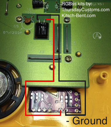
Is it only the Variable Clock that's not working? Try hooking it to these points like this:

And actually it sounds like you might have 5V and GND backwards. That would cause the Game Boy to not turn on.

Last edited by thursdaycustoms (May 1, 2013 8:06 pm)

Offline
Austin, TX

Yeah the variable clock is the only mod at the moment that is causing trouble, when it's not connected the GB runs normally with all the other mods. But I already have the D-pad & A/B LED's connected to the cap in the pic, so would the var clock still work if connected there? I'm certain that the wires weren't mixed, unless the labeling on the pcb is somehow incorrect. I've had trouble on previous GB's when hooking up mods (usually LED's) to the +5v pin going to the power board, and it draining too much power during the booting process.

Offline
Cleveland, OH

Yeah the only other thing I can think of is that you're drawing too much power.
Try disconnecting the LEDs then connect the VCv3.
If that still doesn't work then I can send you a replacement VCv3.

Last edited by thursdaycustoms (May 3, 2013 2:45 am)