When I read your thread title I was intrigued by the mention of RPG Maker, but I was nonetheless expecting something more like a traditional animated music video, so it was a pleasant surprise to see the inclusion of dialogue and a storyline (many modern music videos do of course include narrative elements, but generally with much less explicit storytelling). I feel that the music in fact takes a back seat within the video as a whole, although this is not necessarily a bad thing. I commend you on your pacing of the dialogue; I have seen many (mostly amateur) videos where it seems like the producer simply hasn't timed the text at all. In a way, watching your video is a lot like watching someone play a fast-paced RPG, but the experience is actually quite different to being a spectator of a video game; it is an interesting coalescence of media forms.
65 May 16, 2014 12:54 am
Re: My first Music Video (RPGVX-ACE) (1 replies, posted in Motion Graphics)
66 May 11, 2014 10:18 am
Re: DMG/Pocket video capture with Arduino or Teensy? (244 replies, posted in Nintendo Handhelds)
Quick update on PS3 Eye capture. The cam itself is awesome! Captures video insanely fast with real good quality. But here's how it captures biverted DMG:
You'll need a macro lens. You could try the kind of adapter designed for smartphone cameras, like this one.
67 May 11, 2014 4:12 am
Re: DMG/Pocket video capture with Arduino or Teensy? (244 replies, posted in Nintendo Handhelds)
Thanks for the information, uXe.
Here is a brief rundown of the options I am considering at the moment.
Microcontroller with Two SPI Buses
This should get the data into the microcontroller, but then we need to think about how to get it out, i.e., to a computer or recording medium. We could possibly try this method out with the one SPI bus on the Teensy, capturing half the pixel data.
FPGA
This is probably the best choice of hardware, but represents a substantial learning investment for me, so it may not be the best choice given limited time.
Logic Analyzer
This would seem to solve the problem of getting the raw data from the DMG to the computer (assuming that logic analyzers can capture data at a sufficient sample rate in non-bust mode). It however doesn't achieve my long-term goal of computerless video capture from the DMG.
Other than the cost and time involved, the decision for me will be partly determined by how useful the hardware and knowledge I gain for a certain approach will be for other projects as well. My time is somewhat limited at the moment, and I will probably do a fair bit of thinking / research before I chose which approach to take.
68 May 11, 2014 3:31 am
Re: Customized gear thread (1,206 replies, posted in Nintendo Handhelds)
[photos]
This is one of my favorites so far. Great to see something innovative / out of the ordinary with the paintwork.
69 May 10, 2014 7:09 am
Re: Dumb question: EMS 64 SMD capacitor replacement? (4 replies, posted in Nintendo Handhelds)
I assume you have an older EMS 64 USB and are interested in putting it in a different case? The newer EMS 64 USB carts have an SMD capacitor there, so it should be possible. I don't know if the value has changed between revisions, though.
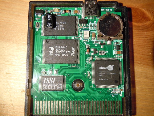
Older EMS 64 USB Cart.
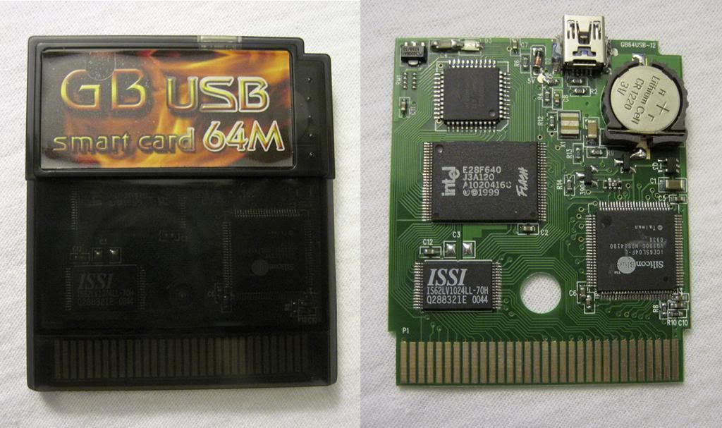
Newer EMS 64 USB Cart.
Images are from the Photos of Gameboy Flash Cartridges thread.
70 May 10, 2014 4:42 am
Re: Looking for a DMG (Non-CGB) Multi-ROM Menu (2 replies, posted in Nintendo Handhelds)
Thanks. I'd had a look around Subport previously, but all the menus there seemed to have CGB support (not that I tried them exhaustively). The source code from the other site was potentially promising; I was thinking I could compile it as a DMG-only ROM. I was then struck with the idea to change byte 0143h of the header of GBPACK.V13 to disable CGB mode, and then recalculate the header checksum. This worked successfully.
That being said, I would still very much enjoy a Color version of Shitwave, especially if it has a Color randomize option.
71 May 9, 2014 3:24 am
Re: Zero budget setup? (34 replies, posted in Other Hardware)
i lookedand i couldnt find a ubuntu download for lgpt... do i just install the regular version?
Use the Debian build from the official site.
72 May 9, 2014 1:43 am
Re: Zero budget setup? (34 replies, posted in Other Hardware)
i don't know if it's able to run on ubuntu natively, but famitracker is pretty user-friendly.
Not natively, but it does run under Wine. LGPT and Milkytracker will also both run natively.
73 May 8, 2014 11:46 am
Topic: Looking for a DMG (Non-CGB) Multi-ROM Menu (2 replies, posted in Nintendo Handhelds)
I have a Doctor 16M cart and have successfully used the GBPACK.V13 menu to make multi-ROMs. These do run fine on an original DMG, but when used in an AGB or CGB (I have only tested in an AGB), they load in CGB mode. This is generally a good thing, as it allows you to use Color games / software. However, it also means that when I am using original Game Boy ROMs in my AGB I lose the ability to change palettes (I especially like the look of Nitro2k01's Shitwave with the various palettes). I can still do this by flashing a single ROM to the cart, but would also like to have this ability when using a menu. Does anyone know of a suitable multi-ROM menu which runs in Game Boy mode (i.e., does not have CGB support)?
74 May 8, 2014 10:12 am
Re: Backlit DMG. What do I need to bivert it? (3 replies, posted in Tutorials, Mods & How-To's)
If you don't want to use a DIP chip, check out the various 'HEX' boards by Thursday Customs, also available from Kitsch-Bent.

Thursday Customs Hex Switch
75 May 8, 2014 9:53 am
Re: circuit bending sega genesis for visuals (11 replies, posted in Circuit Bending)
this is what it looks like i believe the chip labeled hm5346zp-12s8 is the vram, is this correct does anyone know?
Yes, this is the VRAM. This should be the pinout:

Info from http://console5.com/wiki/Genesis.
76 May 7, 2014 10:59 am
Re: circuit bending sega genesis for visuals (11 replies, posted in Circuit Bending)
You can always try shorting out the address lines (or data lines) on the RAM, especially if you can get at the VRAM in particular.
77 May 7, 2014 9:34 am
Re: DMG/Pocket video capture with Arduino or Teensy? (244 replies, posted in Nintendo Handhelds)
Sure, sorry guys I'm just loaded with work lately so things keep slipping off my mind. Here's the code (I know Jazz won't approve):
(Teensy only, won't work on Arduino)
Timer based
uXe has more or less said this, but I realized while I was out today that the reason your code doesn't work is probably because calling the timer ISR takes too long -- it will suffer from the same problems as external interrupts.
2. I PM'ed Nitro about clock master and here's how he'd go about it:
Nitro2k01 wrote:You need a loop, where you do something like the following. This assumes digital pin 0 is connected to the clock input of the Gameboy.
PORTD |= 1; // Turn on clock signal
(Wait a little and/or do something.)
PORTD ^= ~1; // Turn off clock signal
(Wait a little and/or do something.)PORTD ^= 1; // Flip clock signal (xor)
(Wait a little and/or do something.)
PORTD ^= 1; // Flip clock signal (xor)
(Wait a little and/or do something.)
This is right, but this code will (probably) only work on an actual Arduino. PORTx is emulated on the Teensy, and so slow. GIPOx_PTOR is what would be used on a Teensy, as uXe describes.
However he also mentions that he's not sure if after all it can help us to get the video and we gonna need to use assembly.
Yes, we're certainly going to need assembly for this approach.
The only one cheap enough viable option is using SGB. What I don't like about this approach (and rvan has already mentioned this) is that we end up with the de-digitized signal that we'll have to re-digitize.
If you're thinking about the SGB, do also consider the AGB + TV Adapter. And I'm fairly confident that some post-processing on the PC side can give us an image very close to the original.
Apart from that it's either FPGA or some cam-corder type. Thoughts?
Using an FPGA sounds like the approach that is most likely to succeed, but I personally know nothing about FPGAs. The learning curve seems more daunting that ARM assembler.
Other thoughts: Is there another means of getting the raw data (the five lines straight out of the Game Boy) into the PC?
Maybe direct control over the clock would be easier to achieve by having the microcontroller generate a variable signal that can be fed into the standard variable clock mod chip (what the potentiometer normally does - not sure if it is wired as a voltage divider or a variable resistor though?) as well as start / stop control over the clock mod - at least then there would be predictability?
I don't think that this would give us enough predictability. What we need to know is more or less at exactly which clock cycle on the microcontroller the Game Boy pixel lines are ready to be read. The microcontroller needs to clock the Game Boy relative to itself, rather than simply to a specific speed, as any clock drift would cause the data to potentially not be ready at the right time.
...or try PWM for the clock?
The Arduino's PWM frequencies are in the 1-10 kHz range, so I don't think this is much use to us. I understand that the Teensy can reach at least 2 MHz, but that's pushing it. I have no idea how much CPU it uses.
Also, don't forget that even though the Teensy 3.1 is 5V tolerant, it only outputs 3.3V - which the GameBoy CPU may or may not like?
A logic lever converter should work fine here, right? Is there any issue with switching them at high frequencies?
Let's also get back to Flashing LEDs solution - there he used 2-SPI bus uC. We could try that. Although I'm not sure we'll be able to send data to PC at the necessary speed...
Getting the data into the microcontroller would still be a significant step forward. What are good options on cheap microcontrollers with two SPI buses?
rvan, you've mentioned that when you put a byte to the array it takes a lot of time. Have you tried sending data directly to PC? This might work but also might introduce some delays (e.g. buffered USB data sent later)
I haven't tried this, but I don't imagine Serial.write((uint8_t)GPIOC_PDIR)
being faster than line[i]; = GPIOC_PDIR.  I'll see what happens, though.  I also
thought about unrolling the for loop and hardcoding the array item addresses,
but I think I would probably need assembly to make this worthwhile.  (This
paragraph exists in a code box thanks to a BBCode bug.)You can call me crazy but uXe's old idea with Play Station eye doesn't seem that bad now. This thing (well, PS3 version for sure) can record data with 60fps. And they are ridiculously cheap these days I've just ordered 2 for $20. They are heavily used by computer vision guys - this is exactly what we need. There are drivers for multiple platforms. So it's an interesting thing to mess with. But I'd call it a spin off of this project.
I'm interested in seeing how this works out. Good luck!
78 May 6, 2014 10:35 am
Re: Making sleigh bells in LSDJ (6 replies, posted in Nintendo Handhelds)
Here is a thing I just made in LSDj that sounds kinda similar. Envelope A2, Shape FF. I don't know if a DMG can handle that many TSP commands in the noise channel though.
I tried it out. My DMG does fine, but strangely my AGB has trouble.
79 May 6, 2014 10:14 am
Re: DMG/Pocket video capture with Arduino or Teensy? (244 replies, posted in Nintendo Handhelds)
Doesn't work for me...
Post your code!
80 May 6, 2014 10:08 am
Re: DMG/Pocket video capture with Arduino or Teensy? (244 replies, posted in Nintendo Handhelds)
The three-pixels-per-byte approach would still mean having to send 7.5kB every frame anyway, not that big a difference.
You're right. I was thinking of four pixels per byte when I did the calculations.
I do agree though that it would become a little complex, may be it could be an idea for the folks who are making plans to produce brand new motherboard PCBs to include dual-port SRAMs on them though!
That's a great idea re the new boards.
rvan could you share a bit more about your shift register approach?
Well, the shift register approach didn't work out, although the code ended up being simpler than I expected. It seems that the Teensy can't keep up, even when the data is coming in eight times slower. Everything works until I store a byte of data in the array. It seems this must be too expensive an operation.
Nonetheless, here is the code. Wiring is in the comments. Hopefully this answers your questions. Let me know if it doesn't and I can elaborate further.
//Author: rvan
//Read 8-bit parallel data from a shift register and send it over the USB
//Serial.  DOES NOT WORK, as storing a byte in the line array is too slow.

/*
     DMG    4017       74HC595    MK20DX256VLH7
     CLK    CLK        SRCLK
            DO8->RST
GND         CE
            DO1        RCLK       PTB0
     D0                SER
GND                    /OE
VCC                    /SRCLR
                       QA         PTC0
                       ..         ..
                       QH         PTC7
*/

#include <WProgram.h>

volatile int i = 0;
uint8_t line[20]; //Using uint8_t here doesn't make any difference.

//These contain the contents of the GPIO register to which the clock
//divider's output is connected to pin zero of.
uint32_t shclk_prev, shclk = 0;

int main() {
    for(i=0;i<=23;i++) {
    //We set all the pins (including those we don't care about) to inputs.
    //We don't know why GPIOx_PDDR doesn't seem to do anything.
        pinMode(i, INPUT);
    }
    i = 0; //For reuse.
    pinMode(16, OUTPUT); //PTB0

    for(;;) {
        //Bitmask is necessary because other lines will be floating.
        shclk = GPIOD_PDIR & 0b1;
        if(shclk_prev==1 && shclk==0) {
            GPIOB_PTOR = 0b1; //Debug, toggle output.
            //This line is the problem.  If we leave it out, PTB0 toggles as
            //expected.
            line[i] = GPIOC_PDIR;
            i++;
        }
        shclk_prev = shclk;
        /*
        if(i==20) {
            Serial.write(line, 20);
            i = 0;
        }
        */
    }
}Another question I have is how do we produce clock signal with Arduino / Teensy?
Although we saw that the DMG's clock crystal produces a sine wave, I am not convinced that this waveform is necessary for the CPU's clock, given that neither the LTC6930 (Kitsch-Bent's easy_CLK) nor the LTC1799 produces a sine wave. Synthesizing a square wave (which should in theory work fine) is as simple as toggling a digital output pin (other waveforms are more CPU intensive).
Edit: Fixed wiring layout indentation.