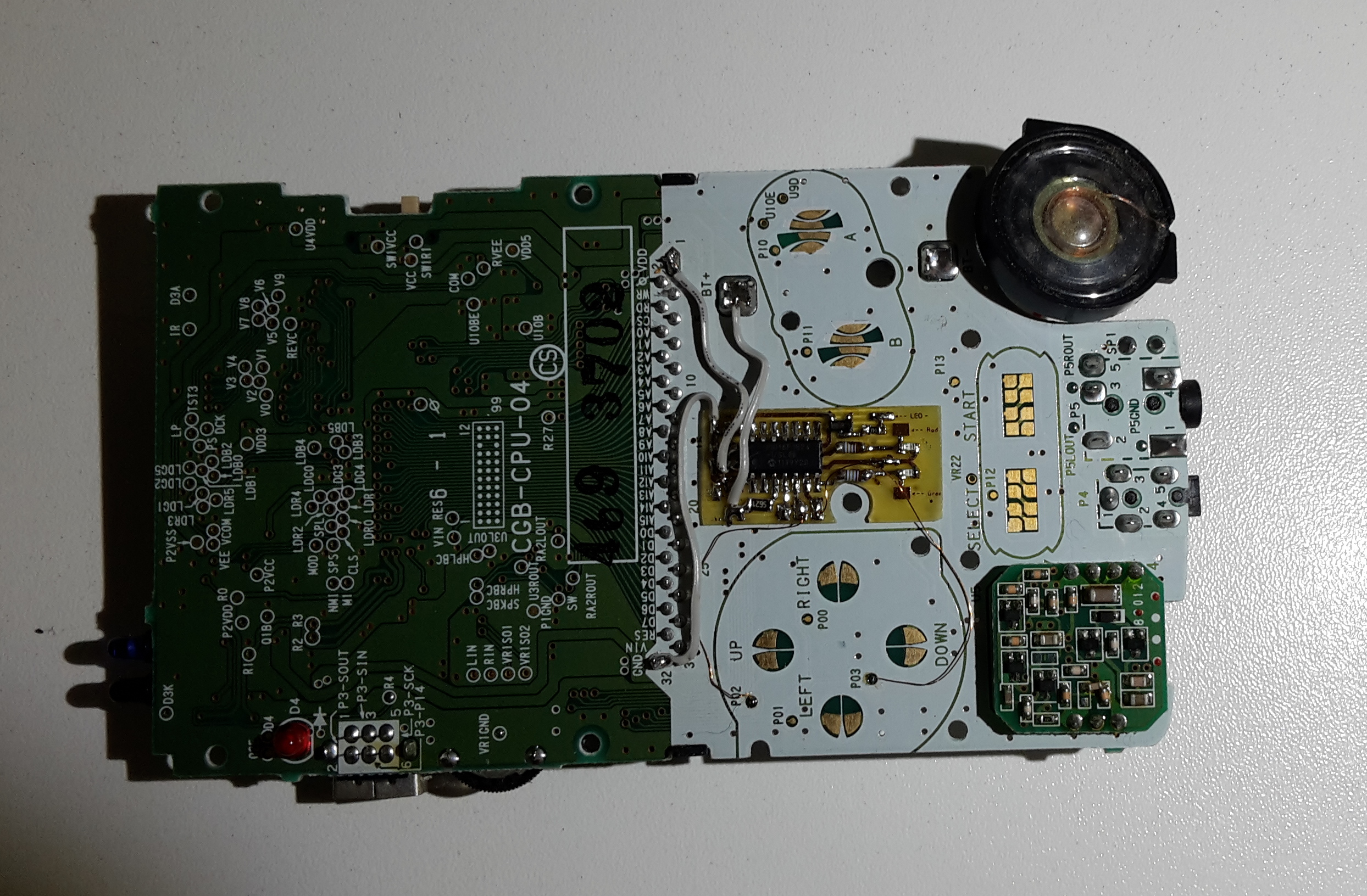
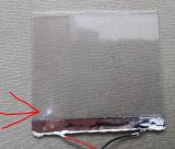
Today, I had my second try, and it worked out pretty well, with one exception, the shitty quality of the front light kits.
I ordered three of these kits and two of them have these spots. They can't cleaned up.

But at least, my brightness control works fine :-)

https://vimeo.com/177447325

I tested the LCD with the pcb of another Gameboy, it didn't make a difference.

Hi everyone!

Today I tried to add a frontlight to my GBC LCD as well as the brightness control pcb I've made, no need for potentiometers anymore wink.
I used Osaka 6 LOCA and a 10W UV LED for curing.
Well, my pcb is working very well, but the LCD isn't working anymore.... It's just blank when switching on the Gameboy, sound is working.
I can't figure out why, there are no mechanical defects. Maybe the LCD became distorted while curing?

In order to save time, money and LCDs, does anybody have some helpful advices, please? BTW, of course I followed these instructions.
http://chipmusic.org/forums/topic/14582 … g-101-mod/


I guess your problem is, that the value of R2 is too high. This circuit is using NPN transistors. For switching they need a current that flows from the base to the emitter. The current that is needed to switch, or in this case to open up, depends on the current gain of the type you are using. If the voltage is high enough, then Q2 gets enough current to switch and held the base of Q1 low. If the voltage drops, then the base-emitter current of Q2 isn't high enough, so there doesn't flow a collector-emitter current anymore. The base-emitter current of Q1 can flow and then the LED lights. Newer LEDs are very bright, so 500µA or max. 1mA should be enough. (2.5V-1.8V-0.2V) / 0.001A= 500Ohm [0.2V is UCE]
You shouldn't use that circuit because there is no trigger, there is no exact level at which the LED lights up. You could use a NE555 (or better a newer CMOS type) if you just want a LED lights up if a voltage drops below a certain value. The 555 is easy to use. There are many sites available that explaining how it works.

I knew about the project by krikzz.
It's been two or three years ago, when I was thinking about buying a SD cartridge for the Gameboy and didn't find anything.
Back then, I thought the efforts to make something like that, can't be compensated by money. I'm thinking the same today. But, there is one thing, that can compensate the effort in doing such a project, it's satisfying my curiosity big_smile
I ran into the whole Gameboy development stuff. Of course it is an old system. The computing power is a lot lower compared to the most available microcontrollers big_smile
But somehow, it's really interesting to me. That's it. I don't think, I could earn money with that project. I guess krikzz will do a great job. However it's just a thing I want to do. It will be a long-term project. Even if it doesn't work proper at the end, it's not like I'll learned nothing wink

Hi,
well, I don't like it to make preannouncement when it comes to projects like this...
However, I'm sometimes kind of a perfectionist^^
That's why I want to collect ideas for the µSD cartridge. Things that MUST BE included and things that can be included optional.
My cartridge will be as cheap as possible but with no compromises related to the functions and the durability(my old DMG is even working these days without problems, it would be a shame, if the cartridge would not work after 25 years big_smile)
Basically it's working with a CPLD that emulates a MBC and to allow the Gameboy to communicate with a SD card.
If I'm done with the work on this project, I'll upload everything about it, so everyone can make her/his own cartridge for private use. It will take some time, so don't ask for the time I need to get it done. It's done, when it's done!!! I'm using a stack memory for storing the games. That is needed, because it is not possible, to load one byte from a SD card as fast as the gameboy is sampling it. The stack memory is pretty cheap. It's including 64MBit flash memory and 8MBit SRAM. I'm using this kind of multi package memory, because it saves a lot of space and makes the pcb layout easier.

These are my ideas:

Things that MUST BE included:

-FAT32 compatibility
-games smaller or equal to 4-MBit will be stored in the SRAM to increase the lifetime of the flash (100,000 write cylces ensured by the manufacturer)
-CPLD does EXACTLY acting as the MBC that the stored game has originally built in (MBC1 or MBC2 or MBC3 or MBC5)
-the name (file name) of the game/program you've played/used the last time will be showed at the top of the list of the games stored on the SD card, so you know what's flashed and so you are able to save writing cycles to increase the lifetime of the flash
-detecting corrupted SRAM and warning(if the battery is running out of juice)
-storing the SRAM data to the SD card (not automatically), storing format will be "romname[NR.].sav" (e.g. "romname1.sav...romname5.sav...") for storing more than one savegame for one game
-loading a specific savegame into the SRAM ("romname2.sav")
-virtual RTC for MBC3 games, it can be configured in the startup menu (if enough space available, I'll built in a real RTC)


Optional things:

-other menu languages than english(I would then implent german and if someone wants to translate the menu, it may be possible to implent other languages)


That's everything for the moment. If I forgot something important, than post it in this thread. No private messages, please.
Of course a Zener diode or simply a comparator would do the job. If I wouldn't work on a frontlight, maybe a small comparator circuit would have been my choice. However, the Nintendo DS is also using a bi-color LED to indicate it's battery state, if I remember right. So I thought, it would be cool to integrate such a function to the GBC because actually, the red LED is COMPLETELY USELESS.
I tested, what's the critical voltage when the GBC is shutting down. I used 2300mAh Ni-MH batteries. The Gameboy was running proper with a voltage of 2.0V, it took approximately 5minutes, then the battery voltage drops to 1.8V and then the Gameboy shutt off. Alkaline batteries should also work at this voltage level, but that depends on the load and the batteries. The real critical voltage may differ. Especially if a frontlight is installed. Due to the higher load the battery voltage drops faster when it's running out of juice. So I guess with a frontlight you don't have 5minutes left until the gameboy stops working.

Reading is helpful...
http://cds.linear.com/docs/en/datasheet/1799fc.pdf

The lack of a proper voltage indicator is really a shame. That's what I've thought too, when I started to work on my DIY frontlight. At the moment, the work on the frontlight isn't done, due to the thickness of the Endlighten T. However, the voltage indicator is working. So If some people are interested only in the circuit and the program for the PIC controller, then I can upload both.