Offline
Jelly Stone park, MD USA
uXe wrote:
uXe wrote:

and then open up a NES joypad and connect the 8 input pins on the joypad's shift register to 8 pins on the Arduino and you'd have yourself a MIDI controlled NES joypad! smile You would even have enough spare pins to connect another 8 to a second joypad if you really wanted to...

...or connect 12 pins to a SNES joypad instead and you'd have yourself a MIDI controlled SNES joypad! smile

Just occurred to me though - not sure if the buttons on the joypad itself could still be functional or if you would need to cut the pins from their previous connections before you wire them to the Arduino... wondering what would happen if you are trying to pull a pin low with the Arduino if it is still being held high by the joypad's built-in pull-ups, or try to pull a pin low by pressing a button on the joypad when it is being held high by the Arduino?

Well you may have a point, will look into this. Off the top of my head, a work-around would be letting the Arduino sacn the KB and then interleave button presses with Midi messages to send to the NES. Haven't looked thru your code, but you are simulating the Game pad with the Arduino? If so, adding a key scan may be possible?
Yog
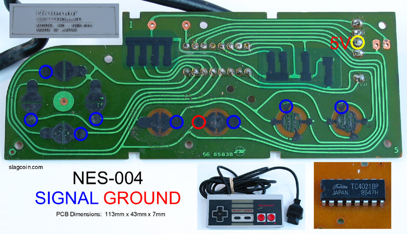
EDIT- Or better yet, setup a SPI read loop for the CD4021. So a ruff setup:
1. Disconnect cable from gamepad board.
2. Connect gamepad board to Arduino SPI pins
3. Connect NES cable to Arduino
Sound workable?

Last edited by yogi (Dec 20, 2013 8:06 pm)

Offline
Melbourne, Australia
yogi wrote:

Thanks for the code!

You're welcome!

yogi wrote:

Got a couple of ProMicro Leonardo clones coming from HK (for another project) so if things workout, you got it!

heart

yogi wrote:
uXe wrote:

Just occurred to me though - not sure if the buttons on the joypad itself could still be functional or if you would need to cut the pins from their previous connections before you wire them to the Arduino... wondering what would happen if you are trying to pull a pin low with the Arduino if it is still being held high by the joypad's built-in pull-ups, or try to pull a pin low by pressing a button on the joypad when it is being held high by the Arduino?

Well you may have a point, will look into this. Off the top of my head, a work-around would be letting the Arduino sacn the KB and then interleave button presses with Midi messages to send to the NES. Haven't looked thru your code, but you are simulating the Game pad with the Arduino? If so, adding a key scan may be possible?
Yogi

No, the Arduino is not simulating a joypad. The FamiiDI shield does have connections to Clock and Latch, but it also has a 4021 shift register onboard - and it is much quicker and easier to just feed the shift register with button presses and let it do its thing than to try and make the Arduino pretend to be a shift register, and be able to keep up with something that is so timing-dependant while it is doing several other things at the same time!

And in the case of the code I have provided for a 'quick and dirty' solution without the FamiiDI shield, the joypad's 4021 is just taking the place of the 4021 on the shield.

You could just as easily buy a shift register IC from any electronics supplier, wire that to the Arduino, and then wire it up internally directly to the NES Expansion Port pins without having to sacrifice a joypad. It is just that a joypad happens to be a quick and dirty way of getting hold of both a 4021 shift register and a cable that lets you communicate with the NES! smile

Last edited by uXe (Dec 20, 2013 8:10 pm)

Offline
Jelly Stone park, MD USA
uXe wrote:

[
No, the Arduino is not simulating a joypad. The FamiiDI shield does have connections to Clock and Latch, but it also has a 4021 shift register onboard - and it is much quicker and easier to just feed the shift register with button presses and let it do it's thing than to try and make the Arduino pretend to be a shift register, and be able to keep up with something that is so timing-dependant while it is doing several other things at the same time!

And in the case of the code I have provided for a 'quick and dirty' solution without the FamiiDI shield, the joypad's 4021 is just taking the place of the 4021 on the shield.

You could just as easily buy a shift register IC from any electronics supplier, wire that to the Arduino, and then wire it up internally directly to the NES Expansion Port pins without having to sacrifice a joypad. It is just that a joypad happens to be a quick and dirty way of getting hold of both a 4021 shift register and a cable that lets you communicate with the NES! smile

Understand. Still seems doable without too much pain. Will think this through a bit.
  A brute force approach could be adding a second 4021, with the arduino in the middle-reading the KB 4021 and outputting a parallel byte to the second  NES 4021.
  Remeber seeing code somewhere of a AVR Gamepad, but this will complicate your code a bit.
Yogi

Offline
Melbourne, Australia
yogi wrote:

Understand. Still seems doable without too much pain. Will think this through a bit.
A brute force approach could be adding a second 4021, with the arduino in the middle-reading the KB 4021 and outputting a parallel byte to the second  NES 4021.

That sounds workable, yes!

yogi wrote:

Remeber seeing code somewhere of a AVR Gamepad, but this will complicate your code a bit.

This would be a good starting point:

http://code.google.com/p/nespad/

Offline
Melbourne, Australia
yogi wrote:

A brute force approach could be adding a second 4021, with the arduino in the middle-reading the KB 4021 and outputting a parallel byte to the second NES 4021.

Another alternative would be to go ahead and cut the shift register input pins from their original connections to the joypad, wire them up to the Arduino for MIDI control, and then make connections directly to the pads on the controller PCB for detecting button presses - read them into the Arduino directly and bypass the shift register! Simple on / off, like how an Atari joystick works - just wire eight Arduino pins to the pads highlighted here in blue, the pins should be held high by the joypad's pull-ups and then when the buttons are pressed those pins should be pulled low:

Last edited by uXe (Dec 20, 2013 11:50 pm)

Offline
Melbourne, Australia

Here's the updated code - a toggle switch connected to pin 12 will select between MIDI or Joypad mode:

EDIT: updated again...

#include <MIDI.h>

int unmappedBend;
byte mappedBend;
static byte bitMask[] = {1, 2, 4, 8, 16, 32, 64, 128};

void setup()
{  
  pinMode(0, INPUT); // MIDI IN

  pinMode(11, OUTPUT); // 4021 D7 (A Button)
  pinMode(10, OUTPUT); // 4021 D6 (B Button)
  pinMode(9, OUTPUT); // 4021 D5 (Select)
  pinMode(8, OUTPUT); // 4021 D4 (Start)

  pinMode(A3, OUTPUT); // 4021 D3 (Up)
  pinMode(A2, OUTPUT); // 4021 D2 (Down)
  pinMode(A1, OUTPUT); // 4021 D1 (Left)
  pinMode(A0, OUTPUT); // 4021 D0 (Right)

  pinMode(A5, INPUT); // A Button
  pinMode(A4, INPUT); // B Button
  pinMode(2, INPUT); // Select
  pinMode(3, INPUT); // Start
  pinMode(4, INPUT); // Up
  pinMode(5, INPUT); // Down
  pinMode(6, INPUT); // Left
  pinMode(7, INPUT); // Right

  pinMode(12, INPUT); // Toggle Switch

  // set OUTPUT pins HIGH
  PORTB |= B00001111; // pins 8, 9, 10 and 11
  PORTC |= B00001111; // pins A0, A1, A2 and A3
  
  MIDI.begin(MIDI_CHANNEL_OMNI);
}

void loop()
{
  if (PINB & bitMask[4])
  {
    if (MIDI.read() && (MIDI.getType() < B11110000))
    {
      if (MIDI.getType() == NoteOn && MIDI.getData2() > 0)
      {
        if (MIDI.getData1() == 60) // C4
          PORTB &= ~bitMask[3]; // A
        else if (MIDI.getData1() == 62) // D4
          PORTB &= ~bitMask[2]; // B
        else if (MIDI.getData1() == 64) // E4
          PORTB &= ~bitMask[1]; // Select
        else if (MIDI.getData1() == 65) // F4
          PORTB &= ~bitMask[0]; // Start
        else if (MIDI.getData1() == 67) // G4
          PORTC &= ~bitMask[3]; // Up
        else if (MIDI.getData1() == 69) // A4
          PORTC &= ~bitMask[2]; // Down
        else if (MIDI.getData1() == 71) // B4
          PORTC &= ~bitMask[1]; // Left
        else if (MIDI.getData1() == 72) // C5
          PORTC &= ~bitMask[0]; // Right
      }

      else if (MIDI.getType() == NoteOff || (MIDI.getType() == NoteOn && MIDI.getData2() == 0))
      {
        if (MIDI.getData1() == 60) // C4
          PORTB |= bitMask[3]; // A
        else if (MIDI.getData1() == 62) // D4
          PORTB |= bitMask[2]; // B
        else if (MIDI.getData1() == 64) // E4
          PORTB |= bitMask[1]; // Select
        else if (MIDI.getData1() == 65) // F4
          PORTB |= bitMask[0]; // Start
        else if (MIDI.getData1() == 67) // G4
          PORTC |= bitMask[3]; // Up
        else if (MIDI.getData1() == 69) // A4
          PORTC |= bitMask[2]; // Down
        else if (MIDI.getData1() == 71) // B4
          PORTC |= bitMask[1]; // Left
        else if (MIDI.getData1() == 72) // C5
          PORTC |= bitMask[0]; // Right
      }

      else if (MIDI.getType() == PitchBend)
      {
        unmappedBend = (int)((MIDI.getData1() & B01111111) | ((MIDI.getData2() & B01111111) << 7));
        mappedBend = map(unmappedBend, 0, 16383, 165, 5); // Arkanoid Paddle range, centered at 170 (+/-80)

        // Paddle Position
        if (mappedBend & bitMask[7]) // A
          PORTB &= ~bitMask[3];
        else
          PORTB |= bitMask[3];
        if (mappedBend & bitMask[6]) // B
          PORTB &= ~bitMask[2];
        else
          PORTB |= bitMask[2];
        if (mappedBend & bitMask[5]) // Select
          PORTB &= ~bitMask[1];
        else
          PORTB |= bitMask[1];
        if (mappedBend & bitMask[4]) // Start
          PORTB &= ~bitMask[0];
        else
          PORTB |= bitMask[0];
        if (mappedBend & bitMask[3]) // Up
          PORTC &= ~bitMask[3];
        else
          PORTC |= bitMask[3];
        if (mappedBend & bitMask[2]) // Down
          PORTC &= ~bitMask[2];
        else
          PORTC |= bitMask[2];
        if (mappedBend & bitMask[1]) // Left
          PORTC &= ~bitMask[1];
        else
          PORTC |= bitMask[1];
        if (mappedBend & bitMask[0]) // Right
          PORTC &= ~bitMask[0];
        else
          PORTC |= bitMask[0];
      }      
    }
  }

  else
  {
    delay(1);

    // read Joypad buttons directly
    if (PINC & bitMask[5]) // A
      PORTB |= bitMask[3];
    else
      PORTB &= ~bitMask[3];
    if (PINC & bitMask[4]) // B
      PORTB |= bitMask[2];
    else
      PORTB &= ~bitMask[2];
    if (PIND & bitMask[2]) // Select
      PORTB |= bitMask[1];
    else
      PORTB &= ~bitMask[1];
    if (PIND & bitMask[3]) // Start
      PORTB |= bitMask[0];
    else
      PORTB &= ~bitMask[0];
    if (PIND & bitMask[4]) // Up
      PORTC |= bitMask[3];
    else
      PORTC &= ~bitMask[3];
    if (PIND & bitMask[5]) // Down
      PORTC |= bitMask[2];
    else
      PORTC &= ~bitMask[2];
    if (PIND & bitMask[6]) // Left
      PORTC |= bitMask[1];
    else
      PORTC &= ~bitMask[1];
    if (PIND & bitMask[7]) // Right
      PORTC |= bitMask[0];
    else
      PORTC &= ~bitMask[0];
  }
}

Last edited by uXe (Dec 21, 2013 1:19 am)

Offline
Jelly Stone park, MD USA
uXe wrote:
yogi wrote:

A brute force approach could be adding a second 4021, with the arduino in the middle-reading the KB 4021 and outputting a parallel byte to the second NES 4021.

Another alternative would be to go ahead and cut the shift register input pins from their original connections to the joypad, wire them up to the Arduino for MIDI control, and then make connections directly to the pads on the controller PCB for detecting button presses - read them into the Arduino directly and bypass the shift register! Simple on / off, like how an Atari joystick works - just wire eight Arduino pins to the pads highlighted here in blue, the pins should be held high by the joypad's pull-ups and then when the buttons are pressed those pins should be pulled low:

My only concern with letting the Arduino scan the buttons is pin count, but it's just doable on a Teensy sized form factor. 16 digital +2 uart pins out of 18 total.
The NESpad lib you pointed to is good, but it seems to use digitalRead and digitalWrite. Which is OK, but burns allot of cycles. I think the AVR's SPI hardware would be a better choice with the 4021, but I may be overlooking something, Will have to play around with some hardware.
The cost of an extra 4021 is small and if the SPI works out it wouldn't slow down your main code much compared to reading 8 pins.
Yogi

Offline
Melbourne, Australia

The way I've re-written the code is to have a toggle switch on pin 12 to choose between MIDI or Joypad mode, so the two modes would never be running at the same time, and there wouldn't be any slow-down to worry about... it seems like having the two modes running at once would cause issues / conflicts with both of them wanting to have control of the same 8 bits?

Also, the code is written with the Duemilanove in mind, so the pin / port values may need to be adjusted for a Teensy - all of the 'genuine' Teensy boards seem to have more than just 18 pins available?

Offline
Jelly Stone park, MD USA
uXe wrote:

The way I've re-written the code is to have a toggle switch on pin 12 to choose between MIDI or Joypad mode, so the two modes would never be running at the same time, and there wouldn't be any slow-down to worry about... it seems like having the two modes running at once would cause issues / conflicts with both of them wanting to have control of the same 8 bits?

Also, the code is written with the Duemilanove in mind, so the pin / port values may need to be adjusted for a Teensy - all of the 'genuine' Teensy boards seem to have more than just 18 pins available?

Cool! Midi or joypad works. Been reading the SPI lib and I think could still read buttons as well as process midi to the NES. Will do some testing.
The boards I order are copies of the Sparkfun ProMicro Leonardo compatible,
https://www.sparkfun.com/products/11098
$5 w/Free shipping (from HK, ugh!) About the same form factor of the Teensy and same AVR, ATMega32u4. Guess I could burn the Teensy bootloader to it (don't even know if it comes with a BL?), but the pin def is a little different.
Yogi

Offline
Jelly Stone park, MD USA
uXe wrote:

Just occurred to me though - not sure if the buttons on the joypad itself could still be functional or if you would need to cut the pins from their previous connections before you wire them to the Arduino... wondering what would happen if you are trying to pull a pin low with the Arduino if it is still being held high by the joypad's built-in pull-ups, or try to pull a pin low by pressing a button on the joypad when it is being held high by the Arduino?

  Going through your sketch, occurred to me, if you toggle the Arduino pins between button Press = 'Outputing' a 0 and button Release = tri-state Input , would be open collector. Not sure how much the AT can drain, but it would work as long as the pad's pull-ups  are high values (low current flow). Not sure if you could Read the buttons, but think you could send button presses to the NES easy.
Will cobble together a test sketch to try this out.
Yogi

Offline
Melbourne, Australia
yogi wrote:

Going through your sketch, occurred to me, if you toggle the Arduino pins between button Press = 'Outputing' a 0 and button Release = tri-state Input , would be open collector. Not sure how much the AT can drain, but it would work as long as the pad's pull-ups  are high values (low current flow). Not sure if you could Read the buttons, but think you could send button presses to the NES easy.
Will cobble together a test sketch to try this out.

Good thinking! Will be interesting to see if it works - the 'resistors' on the joypad are 38kOhms.

Offline
Melbourne, Australia

Although reading in the buttons would have its advantages too - you could write code to implement 'turbo' modes etc!

Offline
Jelly Stone park, MD USA
uXe wrote:

Although reading in the buttons would have its advantages too - you could write code to implement 'turbo' modes etc!

First thoughts could be:
void setup ()
{
  pinMode(x, INPUT); // for all the CD4021 pins
  PORTB &= b00000000; // Arduino pins 8, 9, 10 and 11; PB0:PB3 to Hi-Z inputs
  PORTC &= b00000000; // Arduino pins A0, A1, A2 and A3; PC0:PC3 to Hi-Z inputs
}
to write a button to NES, with 0x00 loaded into the output port latch
  pinMode (pin, OUTPUT) ; // 'button' press
or DDRB = (1<<PBx) // Change pin to output
and then to release it
  pinMode (pin, INPUT) ; // 'button' release
or DDRB = (0 << PBx) // Change pin to Hi-Z input

To read from a pad button
  PORTx |= _BV[x] ; // while in input mode, set bit
read pin and store the bit
  PORTx &= ~_BV[x] ;  //  back to Hi-Z, clr bit
EDIT- After thinking over the above snippet, there shouldn't be a problem just reading the pin; Hi-Z is only relevant to not loading a shared connection. With the external pull-up, the button should only be one of two states, and pose no problem just reading the pin.

Internal pull-ups are "between 20K to 50K", so that would be ~38K in parallel with 38K=19K of pull-up, should be good. We'll see
Yogi

Last edited by yogi (Dec 22, 2013 6:24 am)

Offline
Melbourne, Australia
yogi wrote:

void setup ()
{
  pinMode(x, INPUT); // for all the CD4021 pins
  PORTB &= b00000000; // Arduino pins 8, 9, 10 and 11; PB0:PB3 to Hi-Z inputs
  PORTC &= b00000000; // Arduino pins A0, A1, A2 and A3; PC0:PC3 to Hi-Z inputs
}

Not to nit-pick, because I know you were just typing this off the top of your head, but I think what you mean is:

PORTB &= ~B00001111;
PORTC &= ~B00001111;

to set only those pins to '0'

yogi wrote:

DDRB = (1 << PBx) // Change pin to output
DDRB = (0 << PBx) // Change pin to Hi-Z input

again:

DDRB |= (1 << PBx);
DDRB &= ~(1 << PBx);

to affect only that pin, otherwise you are changing all of the bits on that port, and with Arduinos that can be bad when some of them are permanently assigned as reset or crystal pins...

Offline
Melbourne, Australia

Which makes the code:

#include <MIDI.h>

int unmappedBend;
byte mappedBend;
static byte bitMask[] = {1, 2, 4, 8, 16, 32, 64, 128};

void setup()
{  
  pinMode(0, INPUT); // MIDI IN

  pinMode(11, INPUT); // 4021 D7 (A Button)
  pinMode(10, INPUT); // 4021 D6 (B Button)
  pinMode(9, INPUT); // 4021 D5 (Select)
  pinMode(8, INPUT); // 4021 D4 (Start)

  pinMode(A3, INPUT); // 4021 D3 (Up)
  pinMode(A2, INPUT); // 4021 D2 (Down)
  pinMode(A1, INPUT); // 4021 D1 (Left)
  pinMode(A0, INPUT); // 4021 D0 (Right)

  PORTB &= ~B00001111; // pins 8, 9, 10 and 11
  PORTC &= ~B00001111; // pins A0, A1, A2 and A3
  
  MIDI.begin(MIDI_CHANNEL_OMNI);
}

void loop()
{
  if (MIDI.read() && (MIDI.getType() < B11110000))
  {
    if (MIDI.getType() == NoteOn && MIDI.getData2() > 0)
    {
      if (MIDI.getData1() == 60) // C4
        DDRB |= bitMask[3]; // A
      else if (MIDI.getData1() == 62) // D4
        DDRB |= bitMask[2]; // B
      else if (MIDI.getData1() == 64) // E4
        DDRB |= bitMask[1]; // Select
      else if (MIDI.getData1() == 65) // F4
        DDRB |= bitMask[0]; // Start
      else if (MIDI.getData1() == 67) // G4
        DDRC |= bitMask[3]; // Up
      else if (MIDI.getData1() == 69) // A4
        DDRC |= bitMask[2]; // Down
      else if (MIDI.getData1() == 71) // B4
        DDRC |= bitMask[1]; // Left
      else if (MIDI.getData1() == 72) // C5
        DDRC |= bitMask[0]; // Right
    }

    else if (MIDI.getType() == NoteOff || (MIDI.getType() == NoteOn && MIDI.getData2() == 0))
    {
      if (MIDI.getData1() == 60) // C4
        DDRB &= ~bitMask[3]; // A
      else if (MIDI.getData1() == 62) // D4
        DDRB &= ~bitMask[2]; // B
      else if (MIDI.getData1() == 64) // E4
        DDRB &= ~bitMask[1]; // Select
      else if (MIDI.getData1() == 65) // F4
        DDRB &= ~bitMask[0]; // Start
      else if (MIDI.getData1() == 67) // G4
        DDRC &= ~bitMask[3]; // Up
      else if (MIDI.getData1() == 69) // A4
        DDRC &= ~bitMask[2]; // Down
      else if (MIDI.getData1() == 71) // B4
        DDRC &= ~bitMask[1]; // Left
      else if (MIDI.getData1() == 72) // C5
        DDRC &= ~bitMask[0]; // Right
    }

    else if (MIDI.getType() == PitchBend)
    {
      unmappedBend = (int)((MIDI.getData1() & B01111111) | ((MIDI.getData2() & B01111111) << 7));
      mappedBend = map(unmappedBend, 0, 16383, 165, 5); // Arkanoid Paddle range, centered at 170 (+/-80)

      // Paddle Position
      if (mappedBend & bitMask[7]) // A
        DDRB |= bitMask[3];
      else
        DDRB &= ~bitMask[3];
      if (mappedBend & bitMask[6]) // B
        DDRB |= bitMask[2];
      else
        DDRB &= ~bitMask[2];
      if (mappedBend & bitMask[5]) // Select
        DDRB |= bitMask[1];
      else
        DDRB &= ~bitMask[1];
      if (mappedBend & bitMask[4]) // Start
        DDRB |= bitMask[0];
      else
        DDRB &= ~bitMask[0];
      if (mappedBend & bitMask[3]) // Up
        DDRC |= bitMask[3];
      else
        DDRC &= ~bitMask[3];
      if (mappedBend & bitMask[2]) // Down
        DDRC |= bitMask[2];
      else
        DDRC &= ~bitMask[2];
      if (mappedBend & bitMask[1]) // Left
        DDRC |= bitMask[1];
      else
        DDRC &= ~bitMask[1];
      if (mappedBend & bitMask[0]) // Right
        DDRC |= bitMask[0];
      else
        DDRC &= ~bitMask[0];
    }      
  }
}
Offline
Jelly Stone park, MD USA
uXe wrote:
yogi wrote:

void setup ()
{
  pinMode(x, INPUT); // for all the CD4021 pins
  PORTB &= b00000000; // Arduino pins 8, 9, 10 and 11; PB0:PB3 to Hi-Z inputs
  PORTC &= b00000000; // Arduino pins A0, A1, A2 and A3; PC0:PC3 to Hi-Z inputs
}

Not to nit-pick, because I know you were just typing this off the top of your head, but I think what you mean is:

PORTB &= ~B00001111;
PORTC &= ~B00001111;

to set only those pins to '0'

yogi wrote:

DDRB = (1 << PBx) // Change pin to output
DDRB = (0 << PBx) // Change pin to Hi-Z input

again:

DDRB |= (1 << PBx);
DDRB &= ~(1 << PBx);

to affect only that pin, otherwise you are changing all of the bits on that port, and with Arduinos that can be bad when some of them are permanently assigned as reset or crystal pins...

Glad you caught this,Thanks. sorry for my confusion.
My poor C skills are showing sad Let this be a lesson: 'Compound bitwise logic and late night posting don't mix'!