This may sound dumb, but did you try messing with the contrast?
Offline
(219) Indiana, USA
Haha dsv yah i checked the contrast. Ill take out the switch real quick but I want it in there when I finish this.Just a minute...
Offline
(219) Indiana, USA
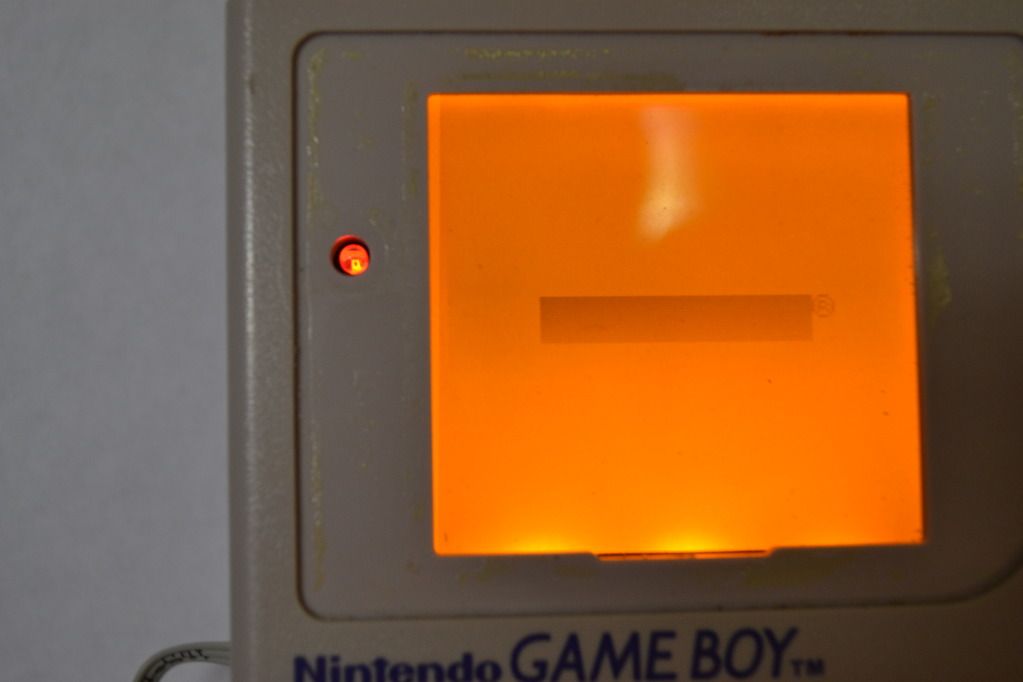
Ok now there are lines that move across the screen and they move faster as the clock gets slower and vis versa. Here's an example:
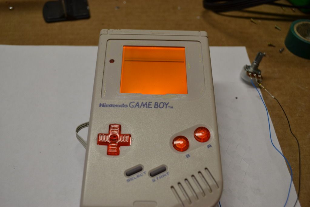
Also the image on the screen only shows up when the potentiometer is set to the lowest speed then it just goes back to lines. Heres what that looks like:
Last edited by zaxxon (Jun 30, 2012 5:07 am)
Offline
I'm saying how does speed compare. it is working if the screen changed. what's sound etc like
Offline
(219) Indiana, USA
the sound is fine and the image on the screen shows the game if that's what you mean when you say it changed.But it doesn't work because it only goes on the slowest speed
Offline
(219) Indiana, USA
but the wave like pulse is on no matter where I turn the potentiometer
Offline
clovis CA
you know that switch wont be any use when you take out that other crystal man
Offline
(219) Indiana, USA
so should I cut the trace and if so where is it? Is there a tutorial or something I could use?
Offline
Cleveland, OH
DO NOT cut any traces!!! When the board is activated it overrides the stock crystal so there is no reason to remove it or cut any traces.
You see those 3 tiny pins at the top left of your picture of the module? You need to connect the middle pin to the ground pad with either a wire or excess solder like this: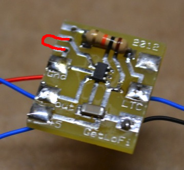
Honestly I really dislike the new version of these kits. They seem really unstable even when installed properly. I had people returning their custom Game Boys from me because these kits would just stop working. I started making my own by hand. I'll have my own model based around the LTC1799CS5 IC soon on a professionally made PCB. It will have a low limiter so that you can manually adjust how low the kit will go when you turn the main pot.
Last edited by thursdaycustoms (Jul 1, 2012 2:39 am)