Haha thanks everyone the pitch mod works now ![]() I just have one more question and that question is where i could put the potentiometer in the casing without getting rid of the speaker.
I just have one more question and that question is where i could put the potentiometer in the casing without getting rid of the speaker.
Bottom left of the face. You can move the two capacitors on the audio filter board, cut the board down and then solder the caps back on with wires. Keep in mind the polarity. Cover them with electrical tape and tuck them in the bottom left with the regulator board.
Last edited by thursdaycustoms (Jul 1, 2012 6:04 pm)
You can also just bend the caps under the headphone board
Not enough room if you're using the standard pot that the kit comes with.
Oh ok. didnt really read the part about cutting the board down.
DO NOT cut any traces!!! When the board is activated it overrides the stock crystal so there is no reason to remove it or cut any traces.
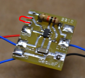
You see those 3 tiny pins at the top left of your picture of the module? You need to connect the middle pin to the ground pad with either a wire or excess solder like this:Honestly I really dislike the new version of these kits. They seem really unstable even when installed properly. I had people returning their custom Game Boys from me because these kits would just stop working. I started making my own by hand. I'll have my own model based around the LTC1799CS5 IC soon on a professionally made PCB. It will have a low limiter so that you can manually adjust how low the kit will go when you turn the main pot.
I know this is an old thread, but I'm really curious about this. You can have a stable switching circuit by exploiting "lazy" electricity by prioritizing resistance, but in this instance, is this something that anyone has taken the time to research and verify to be stable? I'm not seeing how connecting two crystals in parallel could be a good idea.
Just curious since you seem confident to skip this step, which from what I remember, is a step from getlofi's tutorial. This should explain why the kit is unstable.
