Offline
Cleveland, OH

I'll be releasing this kit for sale on my site in a week or two.
thursdaycustoms.com

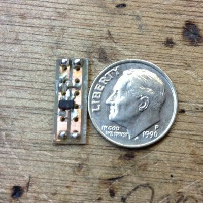
It has an adjustable low limiter and mounts right to the inside of the shell. You can also easily change out the SMT "high limiter" resistor to change how fast it will go or if you need it for a CGB or any other kind of device.

Check it out.

Vimeo:
https://vimeo.com/45031779

Youtube:
http://www.youtube.com/watch?v=gHV7cbHpcSU

Last edited by thursdaycustoms (Jul 22, 2012 5:13 pm)

Offline
clovis CA

I have something similar to this.. i had all the EAGLE files ready to be sent, but then a new car sounded better haha, looks pretty sweet. question. is the smt pot just in series with the other pot? also, hows the stability on it?

Offline
Cleveland, OH

It's parallel. Basically limiting how much resistance the main pot will do. The kit is perfectly stable. I use a higher quality IC than most. I don't mean to bash GetLoFo but I've had nothing but problems with their new revision. That's why I started to make my own. I was hand carving the boards at first but I wanted something more efficient and professional that I can use in commissions and sell to other modders.
I'll also have a V3 that will be entirely panel mount with a micro pot to fit perfectly on the side and the pot will be in a more natural spot for playing live and such. The speaker will not have to be removed.
And then I'll of course have the V1 which will be a standard PCB with easily replaceable resistors for high limit and low limit. I'll probably sell pots and switches separately on the site so you can just order a full kit. I highly recommend solid core wire at least for the output signal. It's far more stable.

Offline
Chicago

First of all, Damn! Very nice work my man.

justinthursday wrote:

And then I'll of course have the V1 which will be a standard PCB with easily replaceable resistors for high limit and low limit. I'll probably sell pots and switches separately on the site so you can just order a full kit.

So does this mean the V1 (GetLoFi version?) is capable of the same things as V2 (or V3?) with additional resistors? If so will these be sold separately so one wouldn't have to purchase a full kit? (I'm assuming the kit includes the PCB)

Offline
Cleveland, OH

In a word; no.
Here's V1:

It will come with an installed SMT 10K resistor for the "high limiter" for typical Game Boy use which can be easily desoldered or cut off and replaced with a through hole resistor or bridged for other devices.
There is a spot for the "low limiter" resistor. I may include a few different resistors with this kit but they will not be pre-soldered.
This will not come with the main pot or the main switch but I will likely make them available on the site separately or make a full kit option.

Here's V2:

The "high limiter" is still replaceable. The low limiter is now a fixed trim pot so that you can adjust the speed before installation or installing it in the way that it's shown in the video for adjusting it with a screw driver whenever you want.
This will not come with the main pot or the main switch but I will likely make them available on the site separately or make a full kit option.

Last edited by thursdaycustoms (Jul 22, 2012 5:16 pm)

Offline
washington

This looks really nice, I'm excited for it. Do you have a price in mind yet?

Offline
Cleveland, OH

I believe v1 will be $10 on its own. Not sure on the other two yet.

Offline

Seriously digging the v3.

Offline

Funny, was working on the same PCB, but with all SMD component.. (not the primary pot , of course)

Also just finished the my selctable GB clock, using 4 fixed frequency (GBclock or GBclock/2, GBclock/4, mGBclock/8)
http://noizeinabox.blogspot.co.uk/

Offline

Ooo very very cool. Pls post when they are up!

Offline
Cleveland, OH

Mine are all SMD parts. But you have the option to switch them out for through hole parts since that's easier for most people.

Offline
clovis CA
xray303 wrote:

Funny, was working on the same PCB, but with all SMD component.. (not the primary pot , of course)

Also just finished the my selctable GB clock, using 4 fixed frequency (GBclock or GBclock/2, GBclock/4, mGBclock/8)
http://noizeinabox.blogspot.co.uk/

love your work man, very clean wink

Offline
new jersey

I was thinking about making a clock control breakout box and it seems like one of these kits will be perfect for it.

However, my goal is to have one clock synchronously controlling multiple gameboys. The plan is to add a female stereo headphone jack wired to the contacts of the gameboy (for each gameboy) and then connect them to the box with a Variable Clock V?. It seems like as long as I'm only drawing the 5v from one gameboy and have the clock out from the kit connected to all of them, the clock speed pot should control all the connected gameboys. Is that right? Does that make sense?

Offline
matt's mind

you'll need independent clocks for each unit, sharing a single clock source split between two units will cause you issues.

you could alternatively just put two clock sources in your box.  you may be able to control them from the same pot or something, that i don't know.  don't see why not.

Offline
matt's mind

justin, your pics went away hmm

Offline
Cleveland, OH

Yeah sorry about that! I deleted all those renders and forgot!
Here's a pic of my working prototype:

I'll be changing a few things like:
The capacitor will only be SMD.
There will only be 2 pot pins. No need got pin 1.
The low limiter will be shifter to the left so when you mount it in the Game Boy you wont have the PCB in the way.
And it will be smaller overall. 3/4" long by less than half an inch wide. The way you can potentially fit it on the other side if you have a 1/4" jack over there as well.

The model in the the video I actually made by hand like this one:

But it was slightly longer to fit the trim pot. Then when I designed it I made it a little bigger over all so it would be easier for people to solder to.

Last edited by thursdaycustoms (Jul 22, 2012 4:25 pm)