Great tutorial! Now, how would we do this with a switch?
Offline
matt's mind
Grayboy wrote:
This is my 2nd/3rd time backlighting my gameboys.
I succeeded the first time.
The second time seemed annoying. And now the third time
has just plain pissed me the F*** off.I have done EVERYTHING correctly. I guess maybe it could be that I'm more
of a musician and not a circuits expert? But the flimsy little wires keep breaking
because of the crammed space. Even before the wires break, I can't get the
LEDs to light up completely. They are dim. Like... Barely-visible-in-complete-darkness dim.Then I messed around with the wires a bit. and then the screen lit up!
Then I tried putting the case on it gently and the screen went dim again.
@*^(#^@#*)^&)@$&^@*$(^(@**DO YOU KNOW HOW ANGRY I AM?! Very very very very angry. Am I using too much solder?
Not enough solder? Are my soldered joints really sh***y? The solder hardly sticks to the wires
and it always sticks to the tip. Then when I turn the heat down, the solder solidifies. Is it my soldering
gun? UGHHHHHHH...>_<
i think the reason you are having soldering issues is that the surface you wish to solder to (the wire) isn't getting hot enough. solder won't flow onto it unless its hot.
this should help out with soldering how-tos: http://store.curiousinventor.com/guides/How_to_Solder
Offline
matt's mind
apt-get wrote:
Great tutorial! Now, how would we do this with a switch?
to add a switch (to turn the light on-off) all you have to do is add one to either of the wires coming from the LED panel. you just need the switch to break, or connect, the electron flow. this will turn the LED on or off.
a simple SPST switch would work.
Offline
Oh sweet. I'm really excited to start modding my stuff...this tutorial's really gonna help haha.
Thanks for clarifying the switch part ![]()
Offline
soo i had my backlight installed for a while and it was working fine. I opened it up and accidentally pulled the resistor from its spot. I soldered it back on and now the light is working but unbearably bright. I can hear the sounds and everything but no matter how i adjust the contrast i can barely see anything. I have opened it up and closed it numerous times trying to resolder all the points but to no avail. Could it be the position of the polarizing lens? whats up? anyone else have this problem?
Offline
Germany, Trier
mhm that was for V1 or V2, because V3 Triple and Ultra come from the underside and the power led is untouched.
but nice tut !
Offline
Barcelona city - Spain
Hi. Got one of the Nonefinite V3 led backlight kits, and I have some questions :
1. On the latest video tutorial http://www.youtube.com/watch?v=pmE3ztwCvcg you mentioned that we have to options to wire the red and black cable (on my kit black cable comes yellow, but doesn't matter ;-).
2. Since I open and close my gameboys regularly, doing other test etc. I would want to wire the red and yellow cables like in the old V2 tutorial (without switching) … So I know the red cable with the kit resistor would be wired on point "A" (please check the attached picture), and I must remove the old resistor before to do that… But how about the other component? I must also remove that component to install the V3 ultra bright kit?
Let me know! I don't want to remove something that maybe don't affect the functionality of these new V3 kit. And I prefer to wire like in the previous kits and not like in the nonfinite video.
Thanks!

Offline
No components need to be removed. there are a couple regulated power sources on the front pcb. One is the leftmost leg of the transistor directly above the three in line caps (in line as in, they make a straight line)
Offline
Austin, Texas
You don't have to remove anything, just cut out part of the plastic LCD frame so that the wires can pass through without being crushed.
Wiring to a power source is a matter of personal preferences. I wired mine to a regulated source. The advantage is that the backlight doesn't dim when your batteries start to go out, but it is a pain in the ass to work on your game boy with one of these installations, because the front board is in effect (semi)permanently attached to the rear board.
Wiring to the front board in the manner of a more traditional installation is easier in that you can disassemble the game boy as your would have originally, but the backlight will dim as the batteries begin to lose power in the same manner that the power LED begins to dim.
EDIT:
12ianma wrote:
There are a couple regulated power sources on the front pcb. One is the leftmost leg of the transistor directly above the three in line caps (in line as in, they make a straight line)
Whoah, I didn't know that… I'll have to redo mine when I see a diagram of what you are describing!
(I think I see the transistor your are talking about in DROP 1410's picture above, but "left" is a relative term… also, I don't know where ground should be connected on the front board.)
Last edited by Telerophon (Aug 22, 2012 9:49 am)
Offline
Barcelona city - Spain
Thanks a lot Telerophon but as 12ianma says... I want to wire into a regulated power source just from the front pcb board.
12ianma would you able to attach a picture... that would be great!, even if I don't want to flame my gameboy :-P
Thanks!
Offline
Austin, Texas
I didn't know there was a regulated source on the front board, so I'll be redoing mine as soon as we get this diagram, too. ![]()
Offline
Germany, Trier
i did my V3 Triple without cutting anything and soldered it to the elko at the bottom of the screen on the front pcb!
Offline
Uh, here lol. As far as grousing, any large exposed piece of metal... Any of those tabs, the outer casing of power switch... the ground of the power led. you name it. 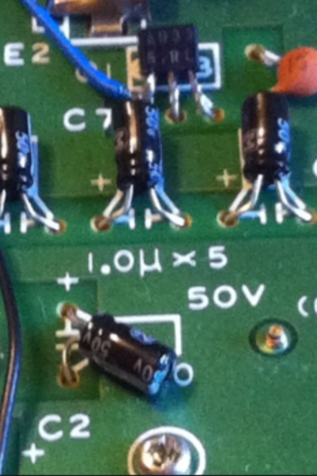
Offline
I would like to thank my man ralph (nex) for the information.