So, I've got something a bit special to share with you guys. Apart from it just being a nifty-cool device, I will be taking you though the build process, or should I say the 're-build' process. I've taken one of my old and early projects and 'remastered' it using techniques/skills I've learned long after I initially made the thing. So this is going to be a sort of before and after type showcase along with just showing off the device itself and the various stages within the re-build. I would also like to ask all of you if y'all have done anything similar with your old projects. Anyone have any similar experiences with reworking an old project using your current and more proficient modding prowess? I'd seriously love to hear your stories about it.
Now without any further blabbing by me, let's get to our feature presentation ![]()
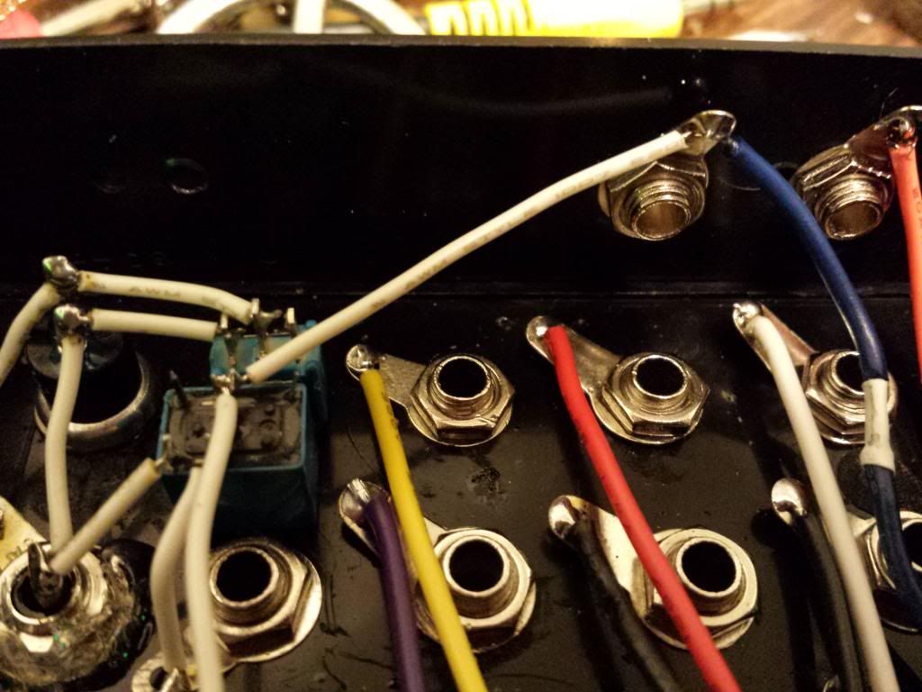
First lets take a look at my original machine. Sorry but I only really have this one photo of it as I didn't expect I was going to be documenting the build process as much as I ended up doing.

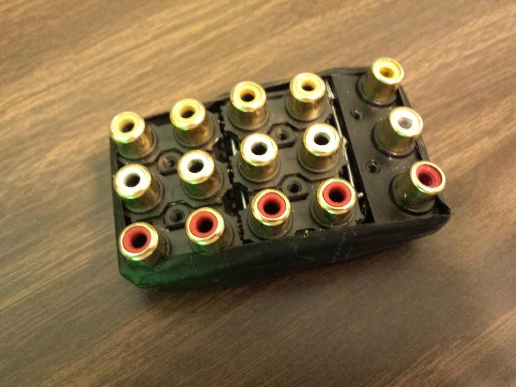
Notice the tape and loose wires? The wires are soldered directly to the bend points and coming right out of a hole in the back. The RCA assembly is merely taped to the genesis. Sure, It looks a bit cool and grungy, but I'm the type of person in which the pride I have for my work is directly proportional to how professional I can make it look.
I was rather inexperienced and had no income, so I used whatever I had available to me. I used components found from inside various devices around my garage and closet. My first instinct was to just do switches like some interesting Speak&Spell bends I had seen at the time, but luckily I had enough foresight back then to know that switches would be incredibly limiting compared to the more modular approach using these RCA connections.
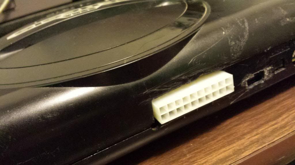
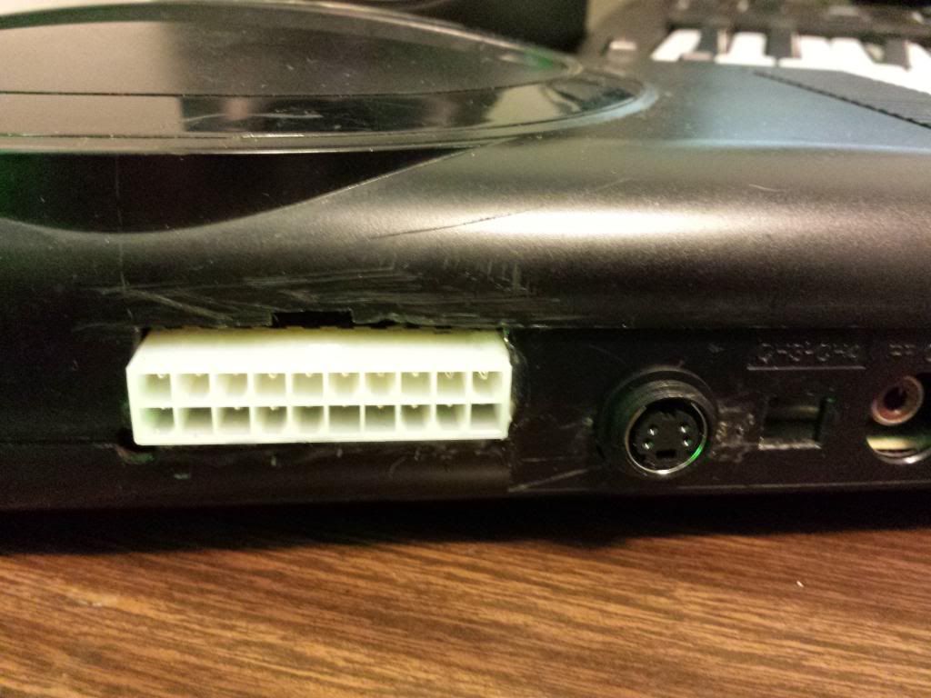
Now the first step I created for myself was to make this thing removable so the Genesis could revert back to it's clean original state. I eventually decided on using a 20 pin molex connection. These are found on nearly every single computer power supply, so I had both male and female connectors already available to me on a dead computer. I just harvested the header from the motherboard and cut the mating connector from the supply. It conveniently already had wires attached so that was clearly the best choice for me.

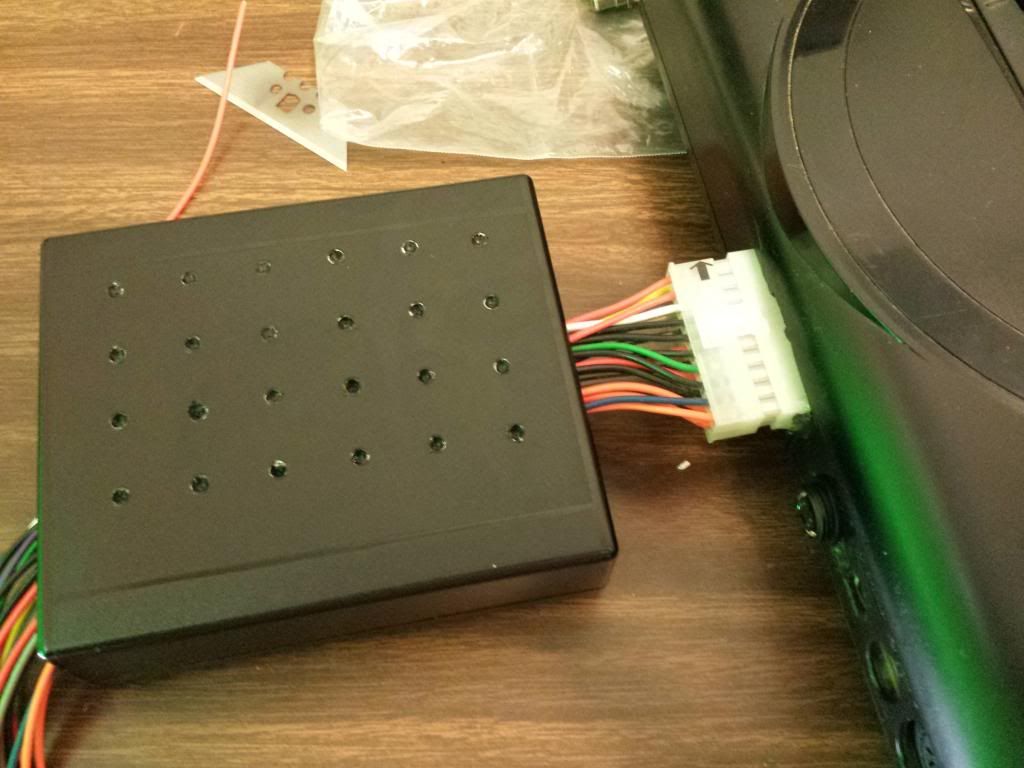
This becoming a removable mod required me to acquire a suitable enclosure for everything. So I did some searching around on Mouser and DigiKey 'till I found a lovely little box close the exact dimensions I needed.
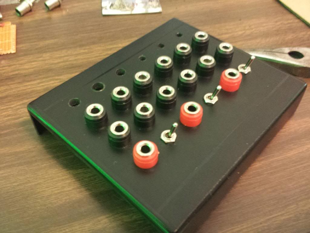
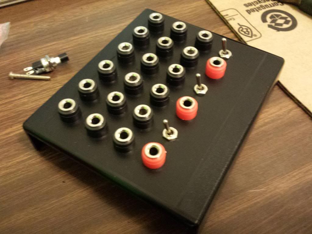
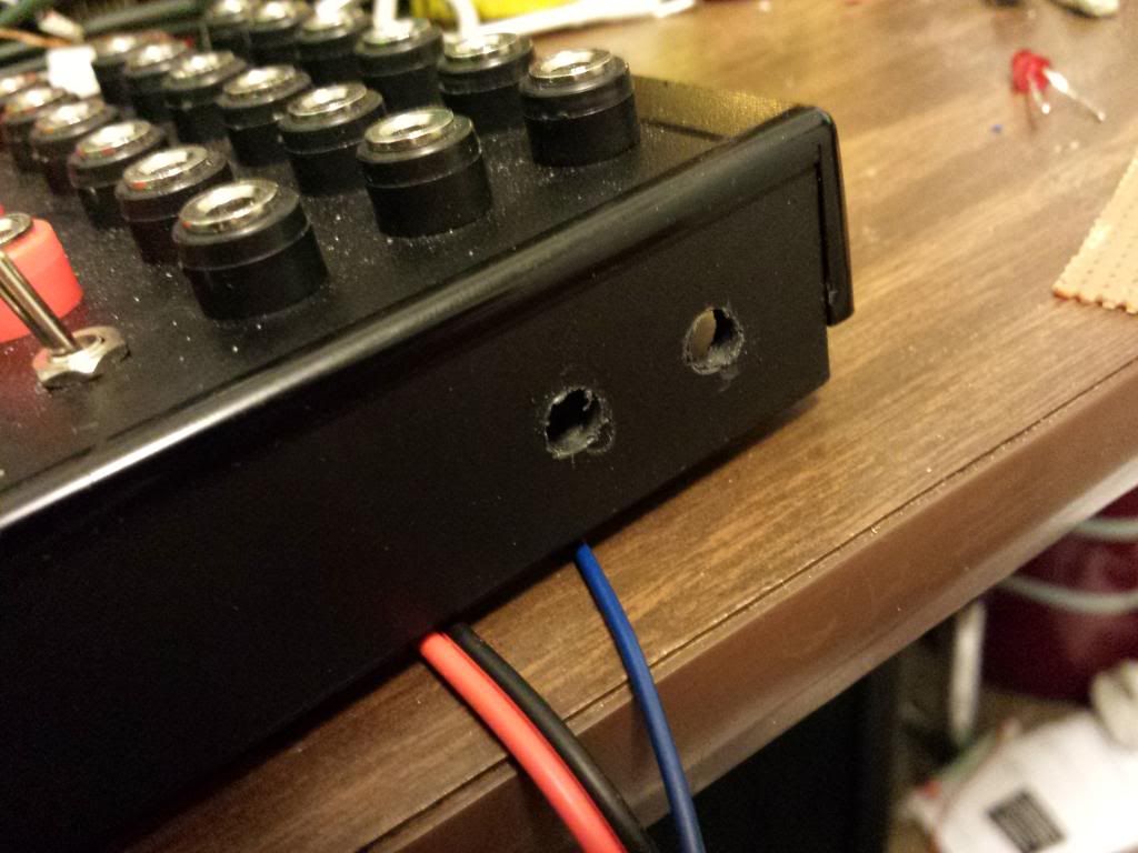
Next I decided that banana plugs were a much better choice than the RCA jacks in my original version. So after those critical pieces were decided on, I could start designing my panel layout. Placing the components derctly on the encloser and taping the sides helped me to more accurately measure where all my holes should go.


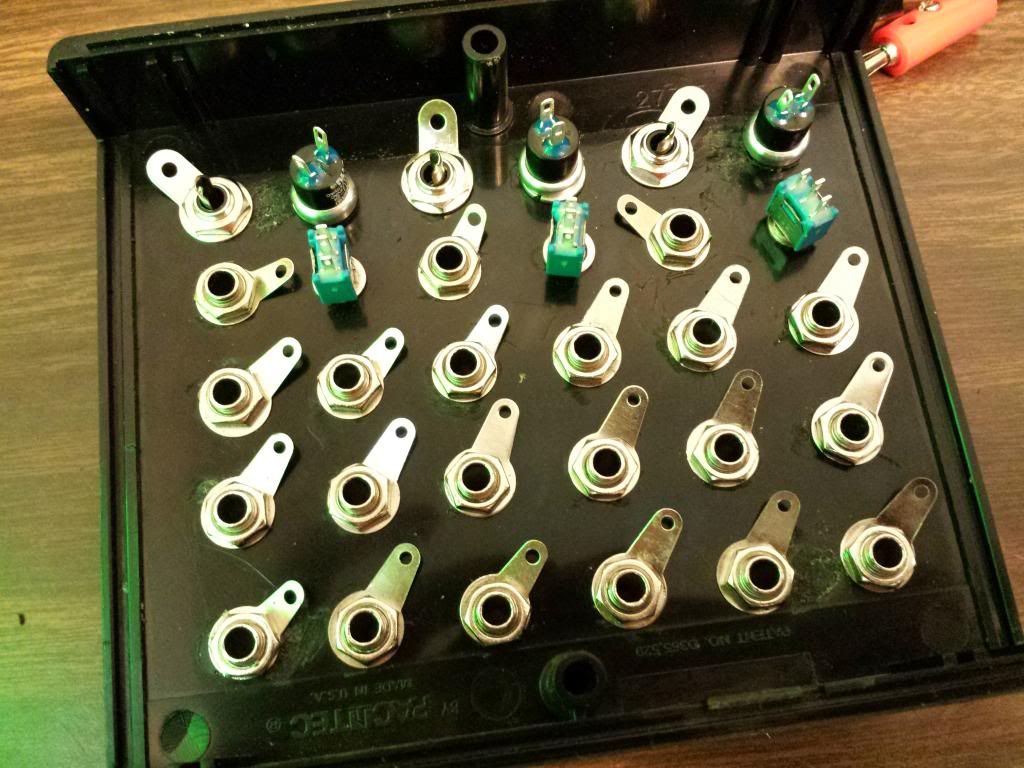
Once I was happy with my configuration and marked the exact location of each hole, I started drilling and placing my parts. In my case I used a dremel to actually make the holes because I could slowly round out each hole in any direction I wanted in case they were a bit skewed or uneven. Power drilling, to me, is just way too quick and final. Once I drill out a hole, it's over in seconds and I'm stuck with whatever unevenness I may have done on accident. The dremel allows me to have a bit more control.

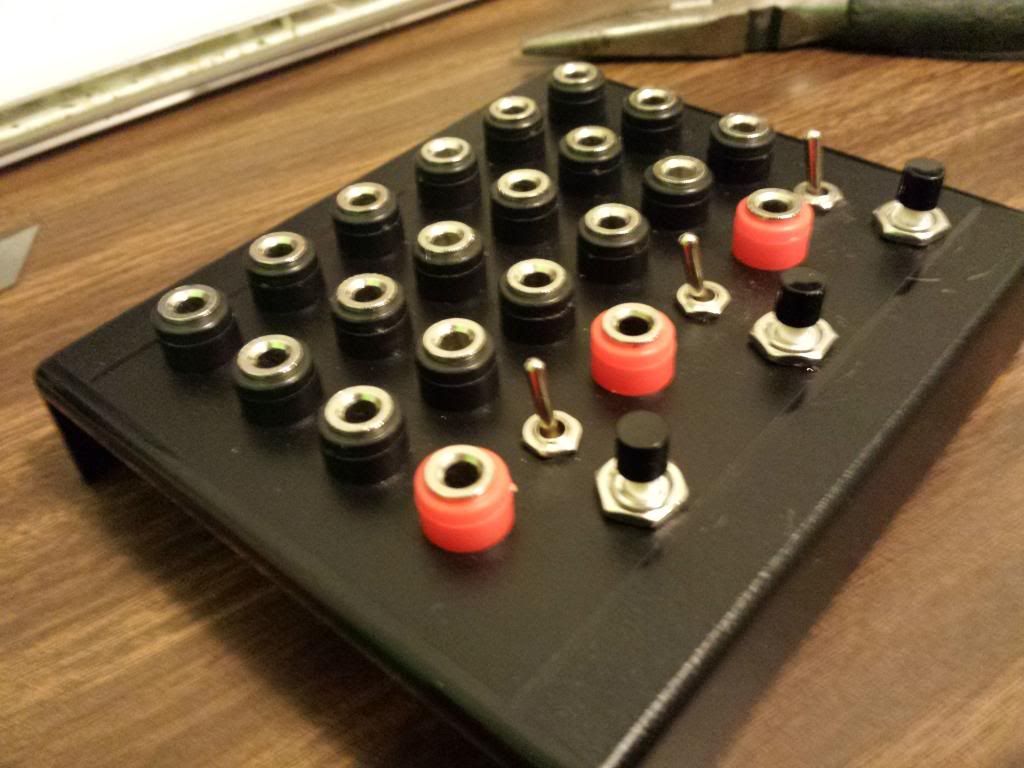

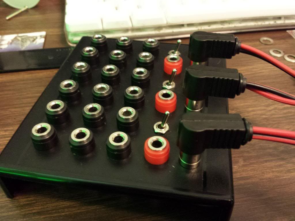
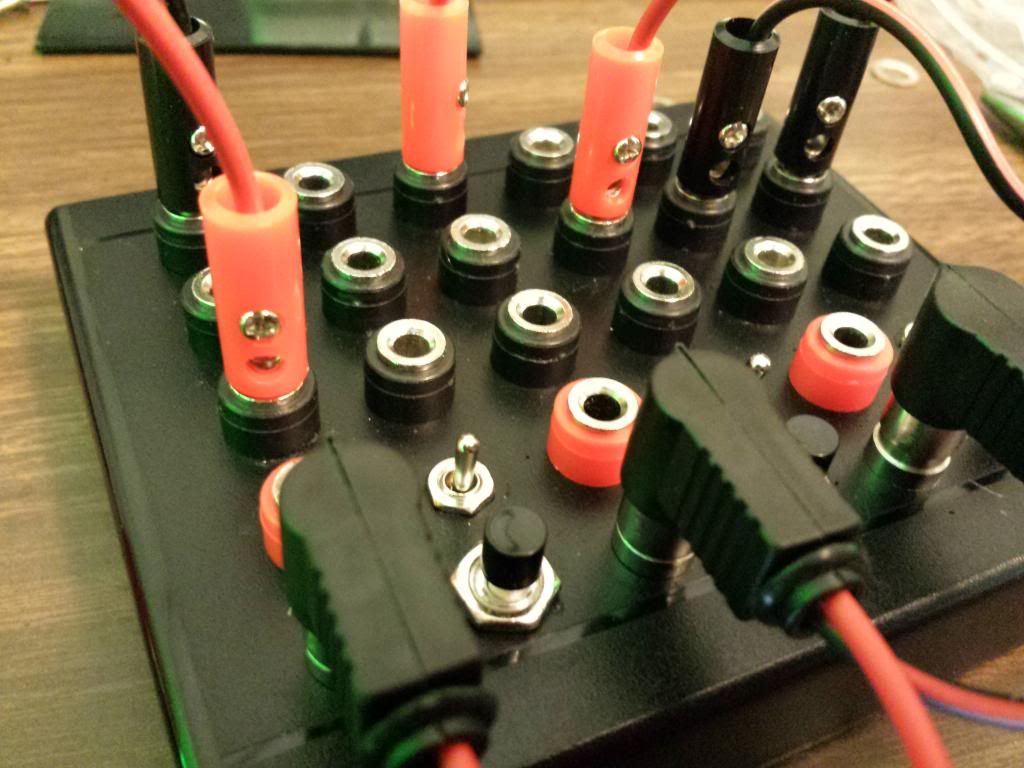
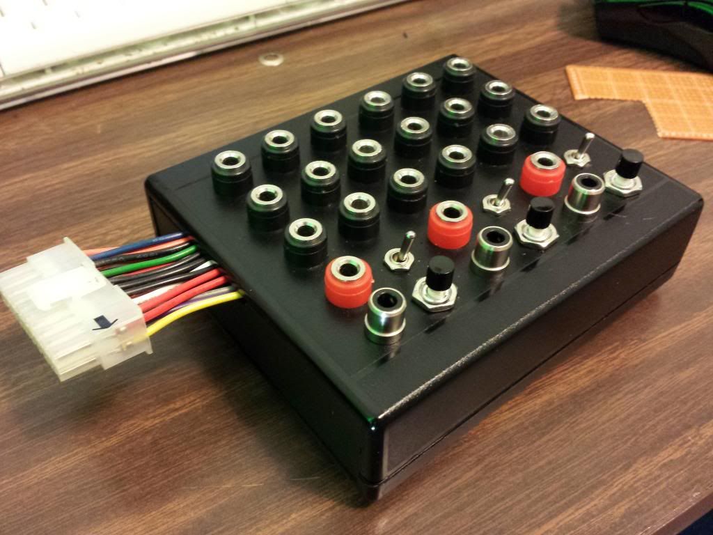
Now that we can see this thing coming together a bit, I can finally start going over the functionality with you. As you have probably guessed the black plugs are the original bend point found in my RCA version. The rest of the switches and plugs might not be quite as obvious to some. So this next piece to the puzzle will make things a lot clearer to those of you still wondering. It plays a very important role in my design.
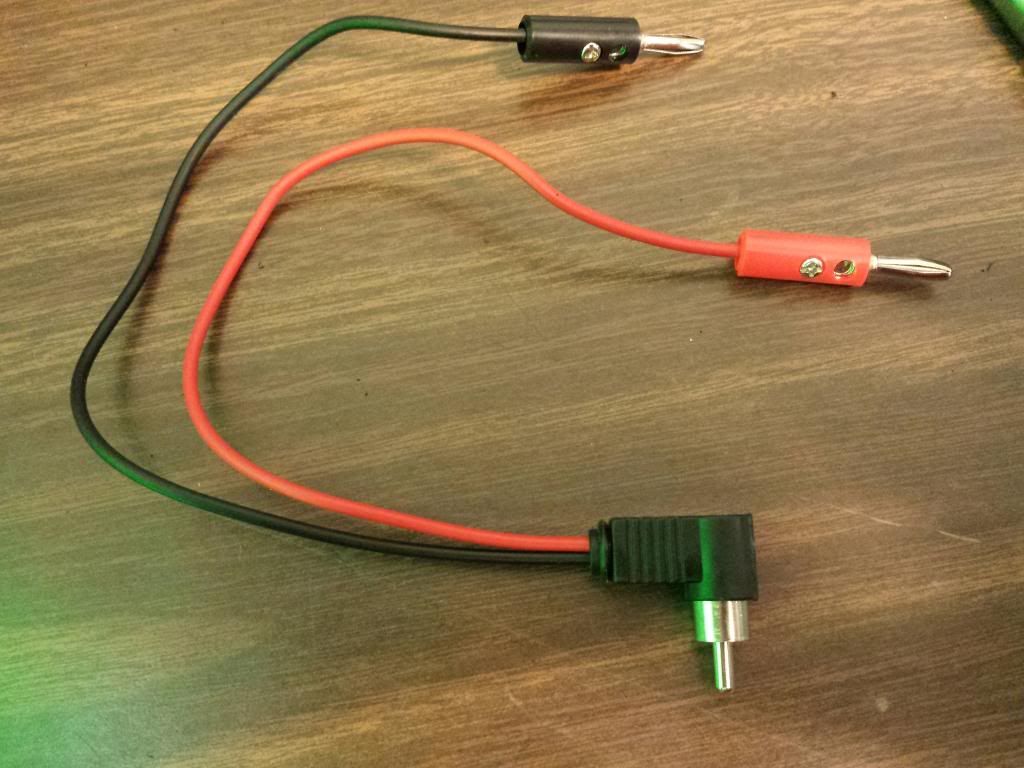
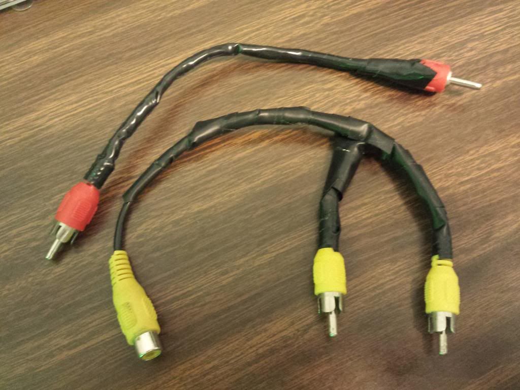
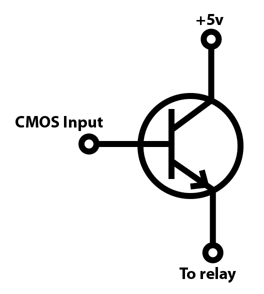
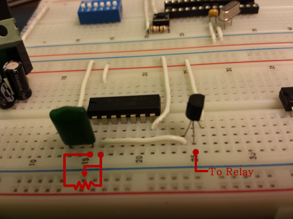
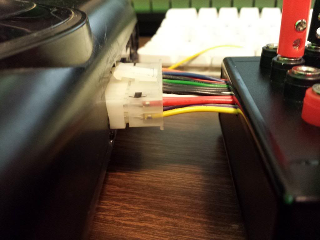
The wire! I created this cable myself for the sole porposes of this project. The RCA connects into my pannel and the banana leads go to any of the black bend points. The actual connection can be initiated in one of three ways. By a momentary pushbutton for VJing in time to music, with a simple switch for making a hands free constant connection, or via the red jacks which are connected directly to the coil pins of 3 relays. So I can feed in the pulses from a simple 40106 clock, a CMOS binary counter, or even use something like an AVR Microcontroller to trigger the relays. One thing to note here is that a raw logic signal from these cmos devices will not be enough to engage the relays. I will have to connect my pulse signal to the base of an NPN transistor and use the collector and emitter to feed a 5v signal to the relay.
› Relay Driver
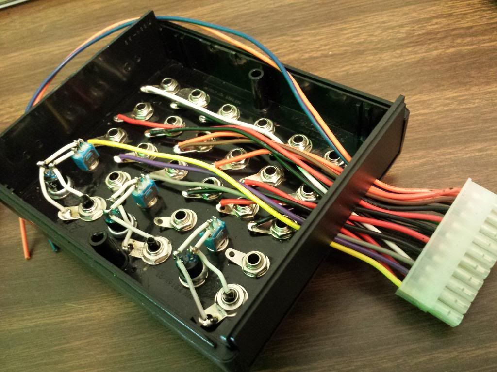
Now that I have the layout done and complete. It is time to wire this baby up! Lets take a look and the under side.
Now to me that looks very neat and clean. LETS KEEP IT THAT WAY. To make that happen I use solid core wire because it will keep its shape fairly well and it's easier to strip with minimal mess. Now in order to keep things as neat and tidy as possible, I only cut my wires to the minimum length required to make the connection.
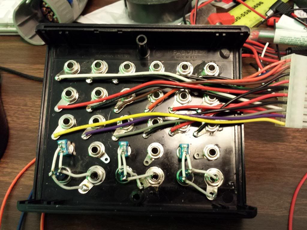
Now if you look down the length of these wires you might notice a bit of spiraling going on.
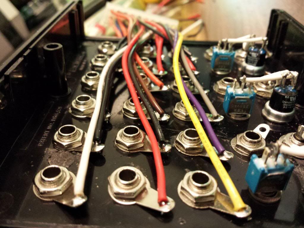
You may be thinking 'Hey Tyler, that doesn't look as neat as it could with the wire laying a bit more flat. What gives?' Now I would agree with you, but the reason for this is because I wanted the order of the jacks to directly match the order of the molex pinout. So jack one on my panel is pin one on my molex. Organisation is more important to me than evenly laying wires. Besides, I still find this implementation very tidy.
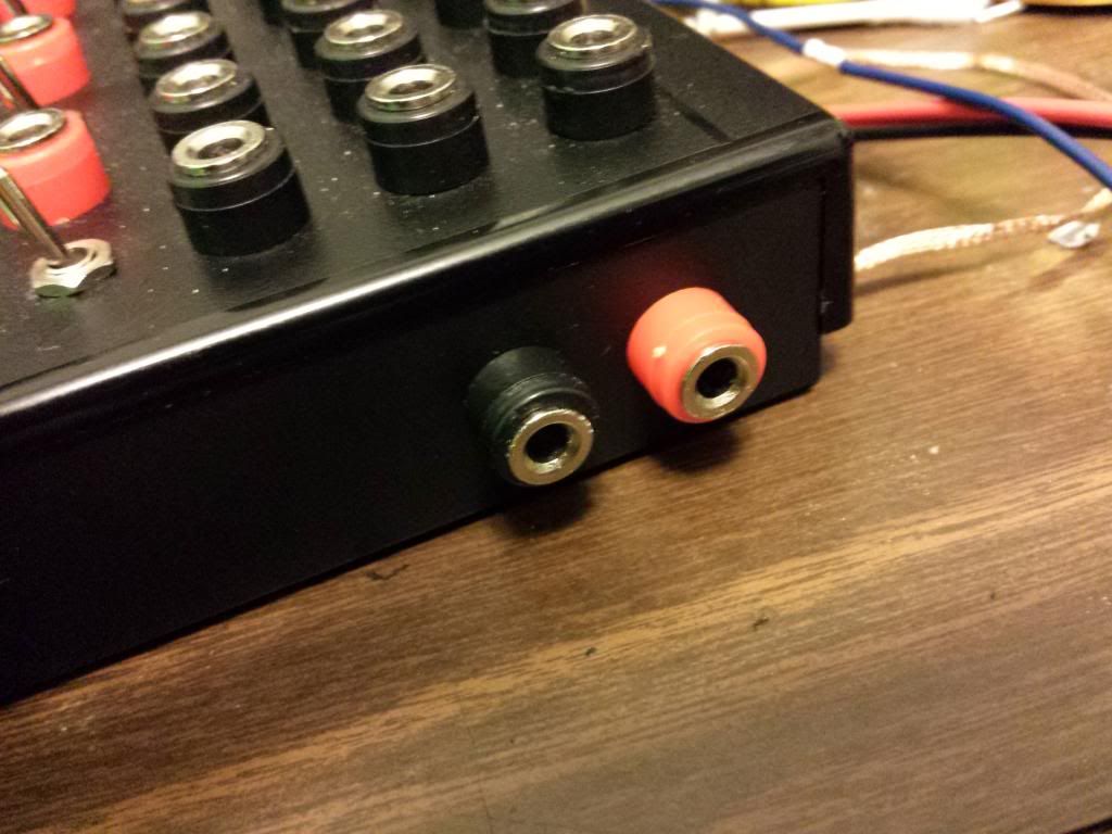
Now I have left two wires coming from my molex unconnected at this stage. These are going to be connected to two jacks that we'll put on the side, giving us access to the +5v, and more importantly, the GND coming out of the Sega. Orange is positive and Blue is ground.
› Quick tip:
I then installed the two banana jacks on the side that will give me access to the Sega's power. The Ground is particularly important because we will need to connect it to the ground of any outside circuit we plan on using the signals from to control the relays. I included the 5v jack incase I want to power these external devices straight from the sega. I really don't like using batteries. Whenever it is possible, I avoid using them. I don't like any consumables that will need replacing down the line. Plus, if it's just a couple cmos chips or a simple micro, the current drawn will not cause any problems to the Genesis.
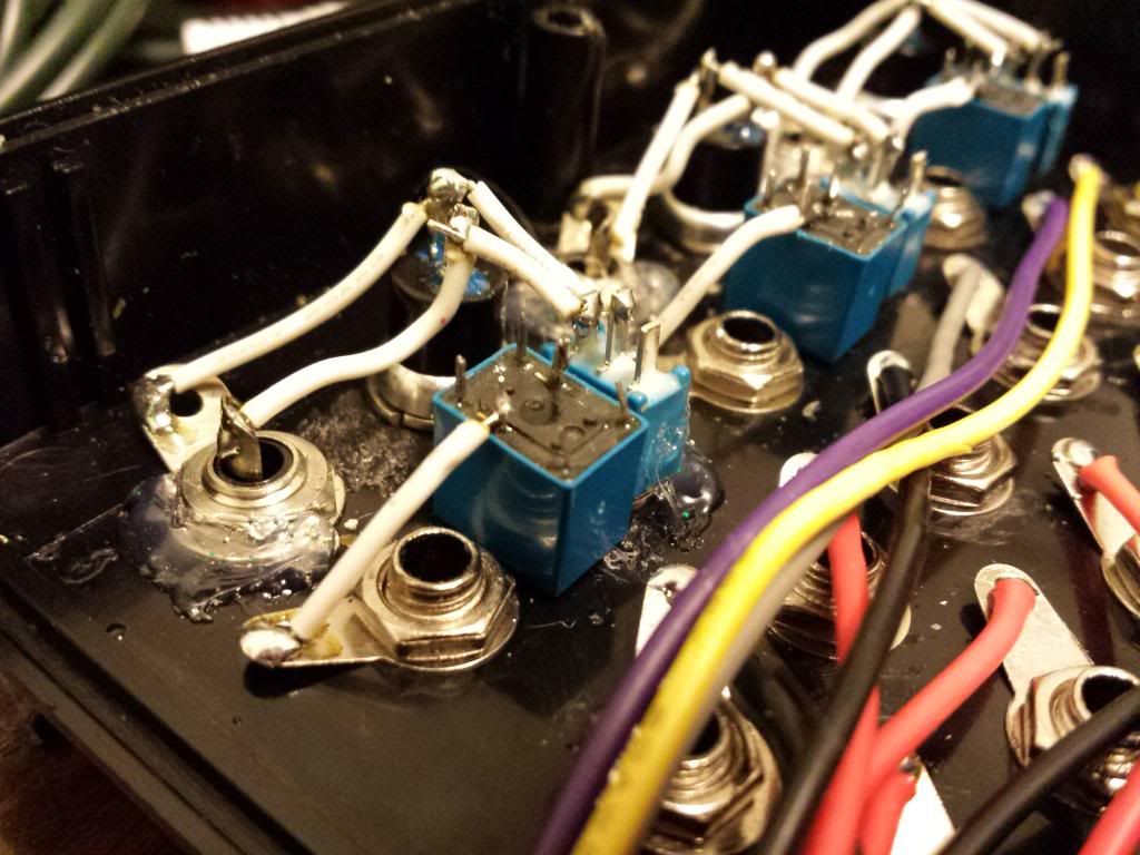
So for the relays, I used OEG OUC-SH-105D relays. they were the smallest I could find for cheap. 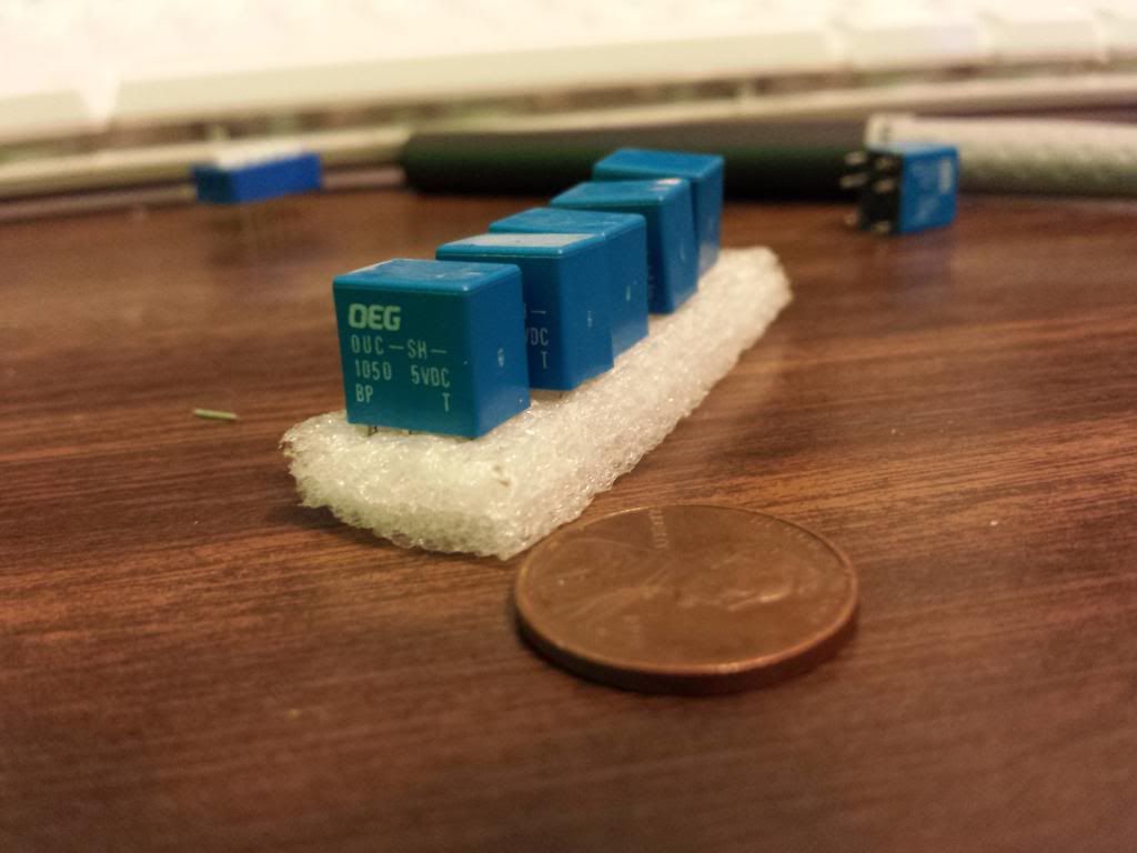
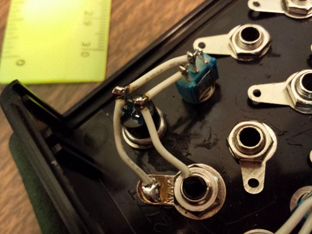
To keep the relays stable, I've hot glued the relays in place next to the toggle switches and begin wiring just as before. You'll notice I also hot glued some other parts down that needed a bit of extra help staying tight and snug on the enclosure.
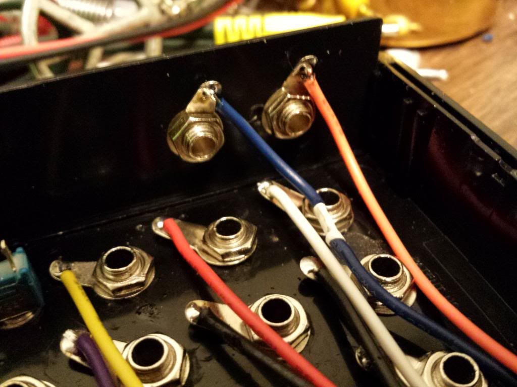
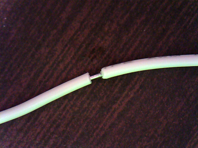
Now there was one wire I did something a bit neat to. For the wire I used to connect all the relay's ground pins, instead of using two wires and soldering both to the middle relay, I stripped the insulation half way down the wire so I could just solder one wire to 3 points. I didn't think of it till quite late in the build, so I wish I had done that on several other connections. It even kind of illustrates what I mean when I refer to the modding skills I have learned over time that initially sparked this re-build. You never know when a new technique will find it's way to you.
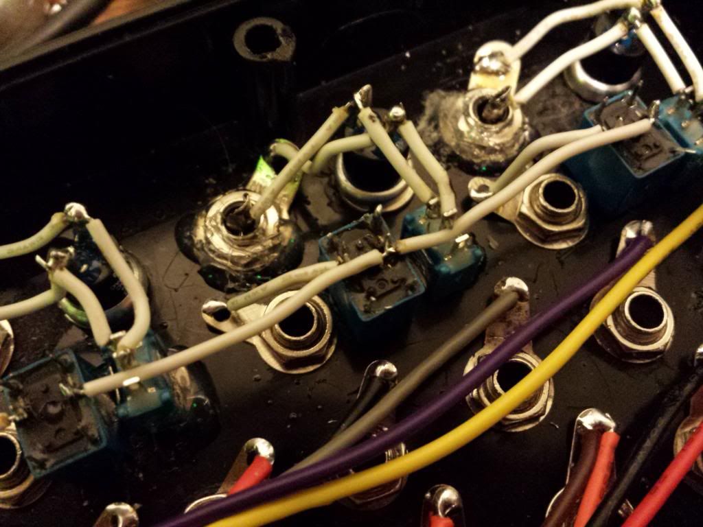
Now I finish up the relay wiring and connect them to my ground jack on the side.

After the relays have been successfully installed, the box is completed. I'm not sure about you, but I very much prefer this over the old messy RCAs. ![]()
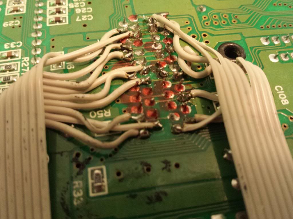
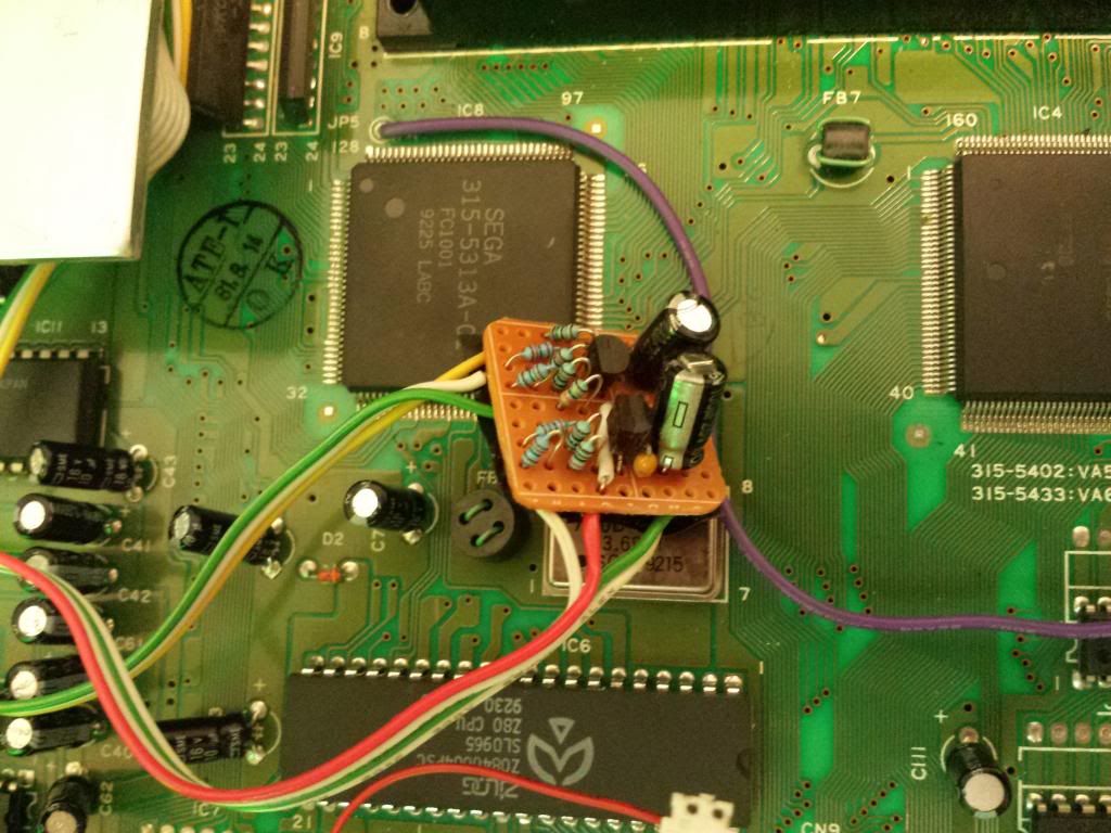
As for the stuff on the Genesis side of things, there actually isn't much to it. Just a ribbon cable from bend points to the molex connector. Thats it. (The orange marks on the solder points are markers for the bends I didn't really care for when I was experimenting)


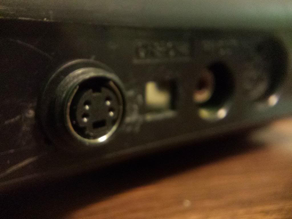
Also, considering this mod is all about the video signal of the Genesis, I obviously wanted to throw in an S-Video mod. No point in glitchin the system if I can't record the video in the best quality possible right?
Heres the schematic I used. The chroma has a 75Ω resistor on the signal output and the Luma uses a 33Ω. 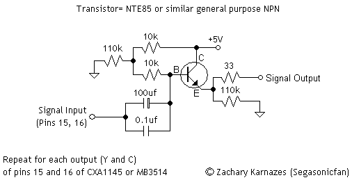
(The rca's pictured on the right were going to be for an alternate audio connection but I decided against it.)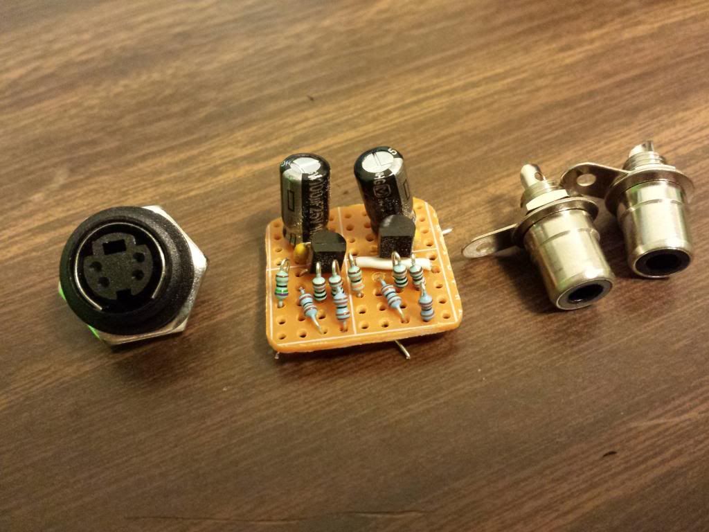
Naturally, I also had to throw in a mega bright blue LED!
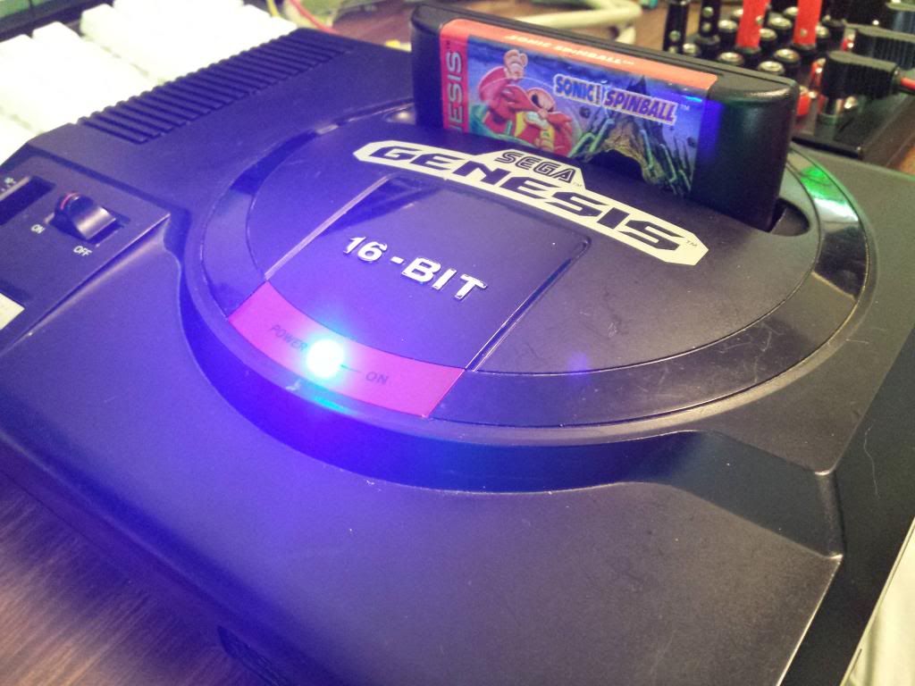
And now finally, lets see this thing in action!
And that, my friends, completes this adventure. I hope you had fun and I hope you learned a few things. I had a great time working on this project again, and it really feels good when something comes full circle and turns out just as expected. Thank you for joining me on the journey!
P.S. If anyone knows of any projects out there that will let me MIDI control the relays, give me a shout! Something that easy to build with little parts would be excellent.
Last edited by TylerBarnes (Mar 3, 2014 9:52 pm)
