PAGE 3 OF THIS POST HAS IMAGES RE-UPLOADED BY A KIND FORUM MEMBER.
Bass Mod and Noise Filtering Mod for the GBC... 56K Death!!!
by Katsumbhong
The purpose of performing these mods is to help give the GBC a clean line-out signal with a bump up in bass frequencies.
Difficulty: Intermediate
This mod requires steady hands to solder very small gauge wires onto SMT components.
Parts Needed:
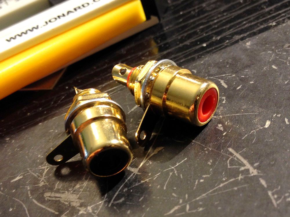
+ (2) Female Chassis Mounted RCAs
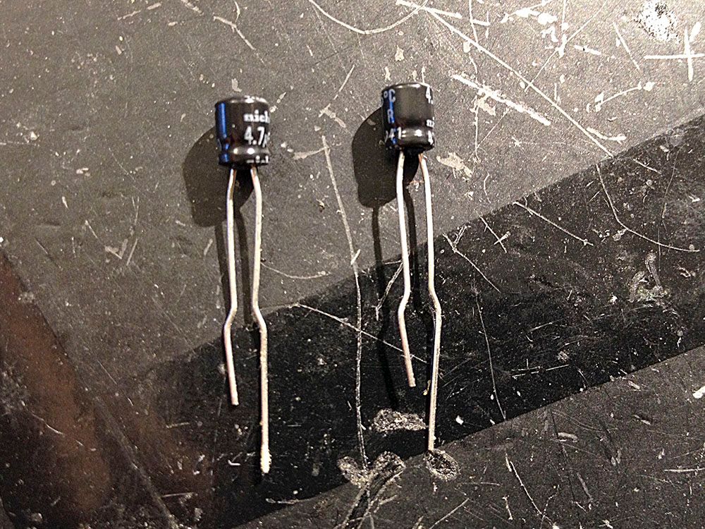
+ (2) 4.7UF 16V non-polar (bipolar) electrolytic capacitors
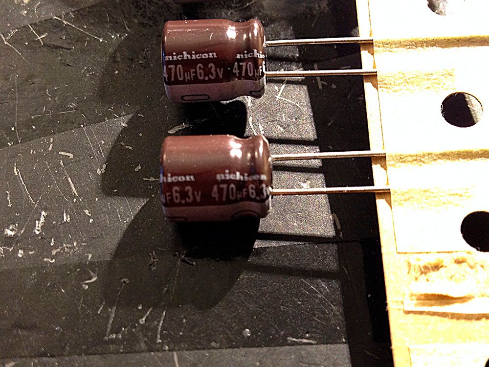
+ (1) 470UF 6.3V polarized electrolytic capacitor
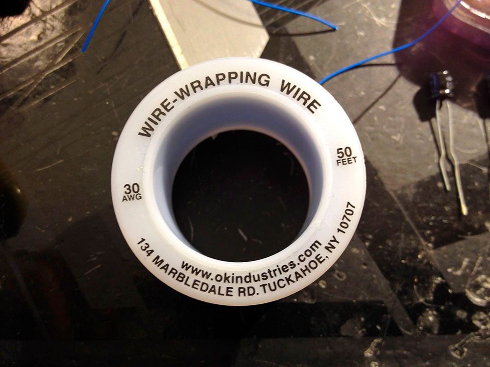
+ 30-gauge wire
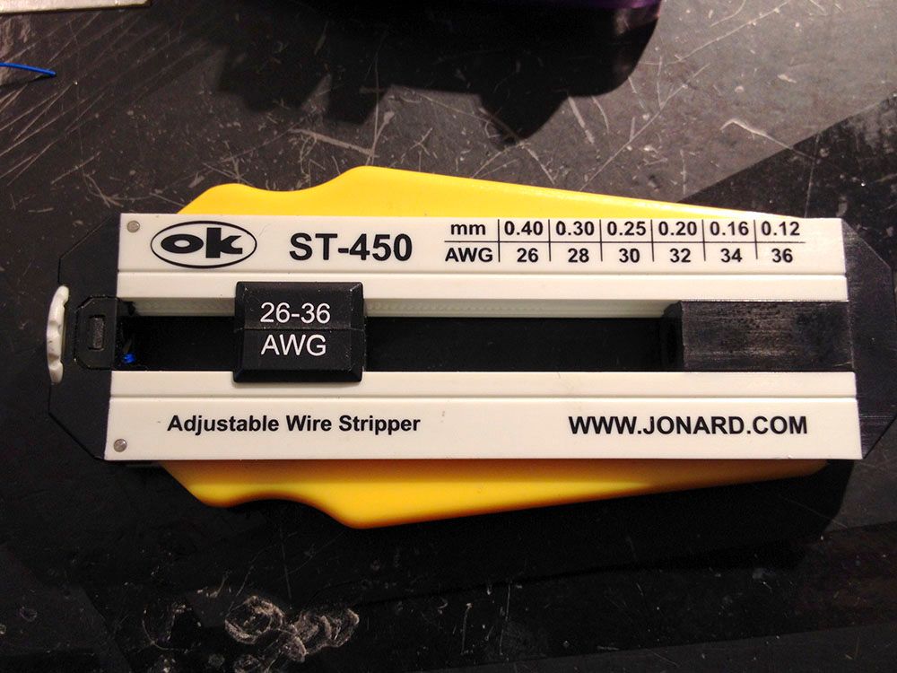
+ Wire strippers for 30-gauge wire
I purchased the capacitors from Digikey. The following are their parts numbers and pricing at the time of writing this tutorial.
4.7uf Capacitors
Digikey
$0.51ea
493-10248-1-ND
470uf Capacitors
Digikey
$1.12ea
493-10387-1-ND
Tools that I used:
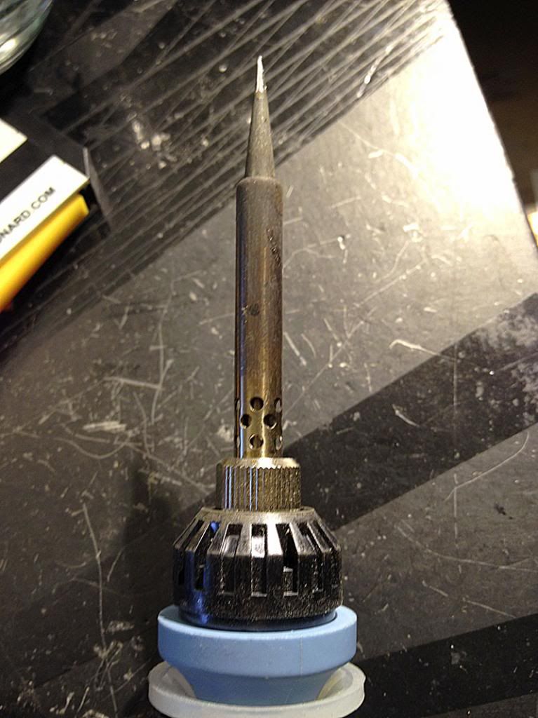
+ Soldering iron with a very fine tip
+ Solder
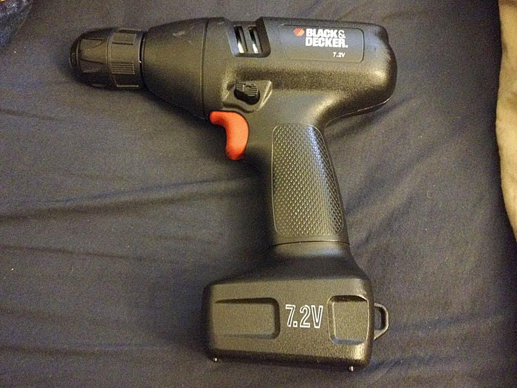
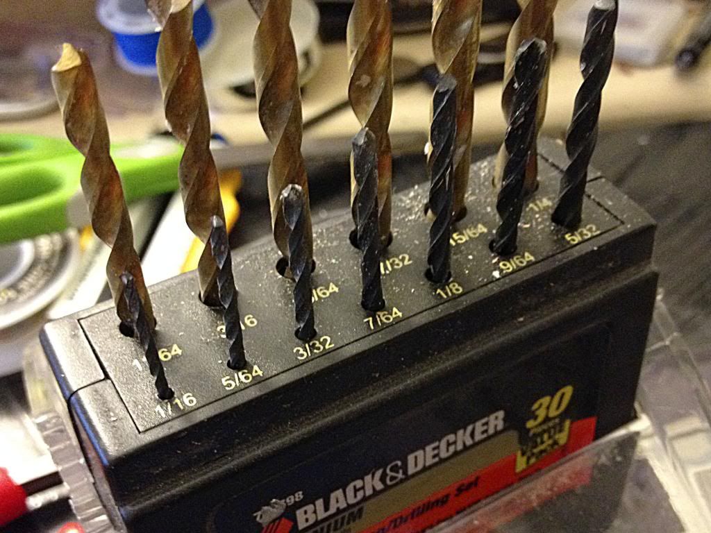
+ Drill w/ drill bits
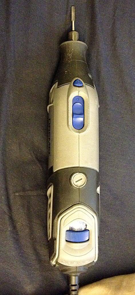
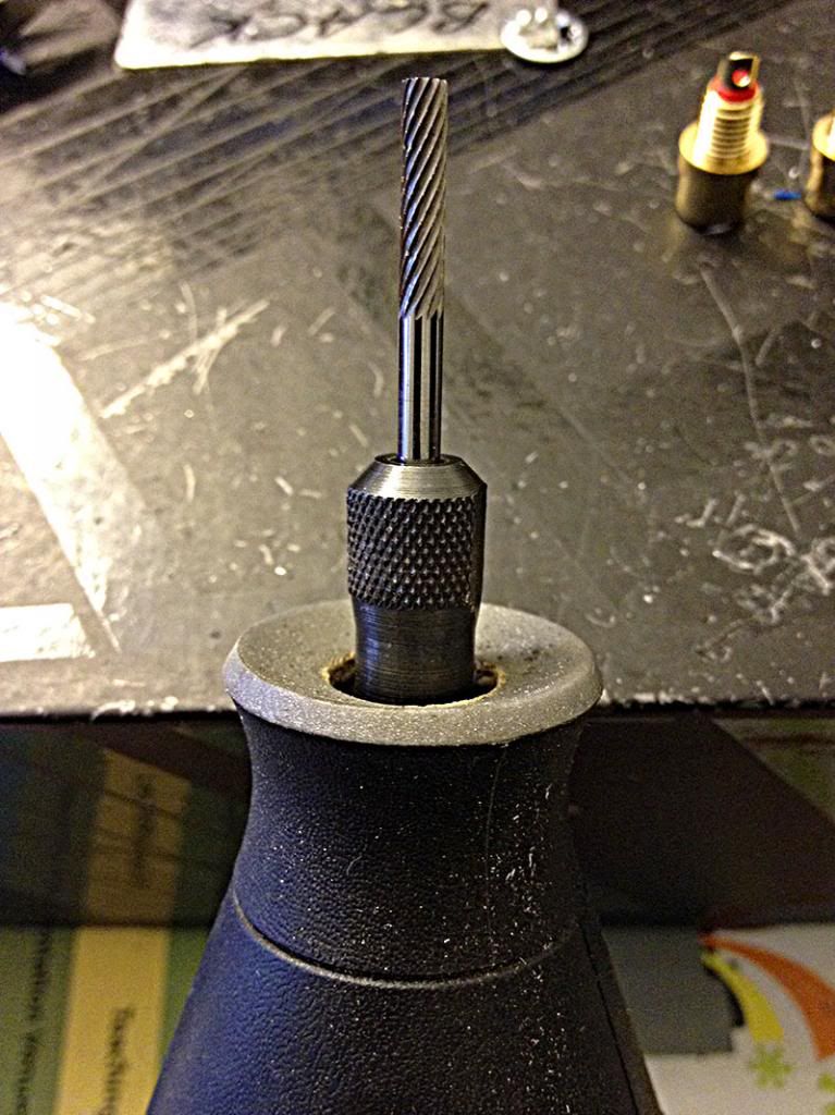
+ Dremel w/ grinding bit
+ Headphone Amplifier
+ Small diagonal cutters or nail clippers
+ Needle nose pliers
+ Shrink wrap
+ Small screwdrivers, flat tip and philips-head
Here we go!
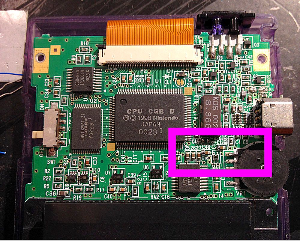
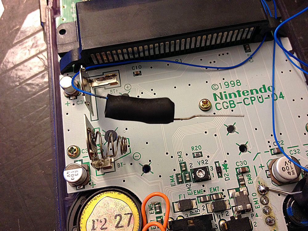
This is the area that we will be focused on for the bass mod.
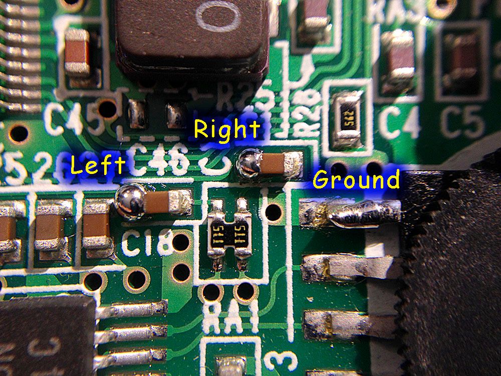
This is tricky. For the left and right output, we will have prep the left side of the SMT components with a small dab of solder. If you remove or damage the connection of these SMT components, you will disconnect the bridge to the speakers and headphones. We will also prep the top tab of the volume potentiometer for ground. You may also alternatively choose to use a different grounding point as you see fit. Make sure to take your time with this step.
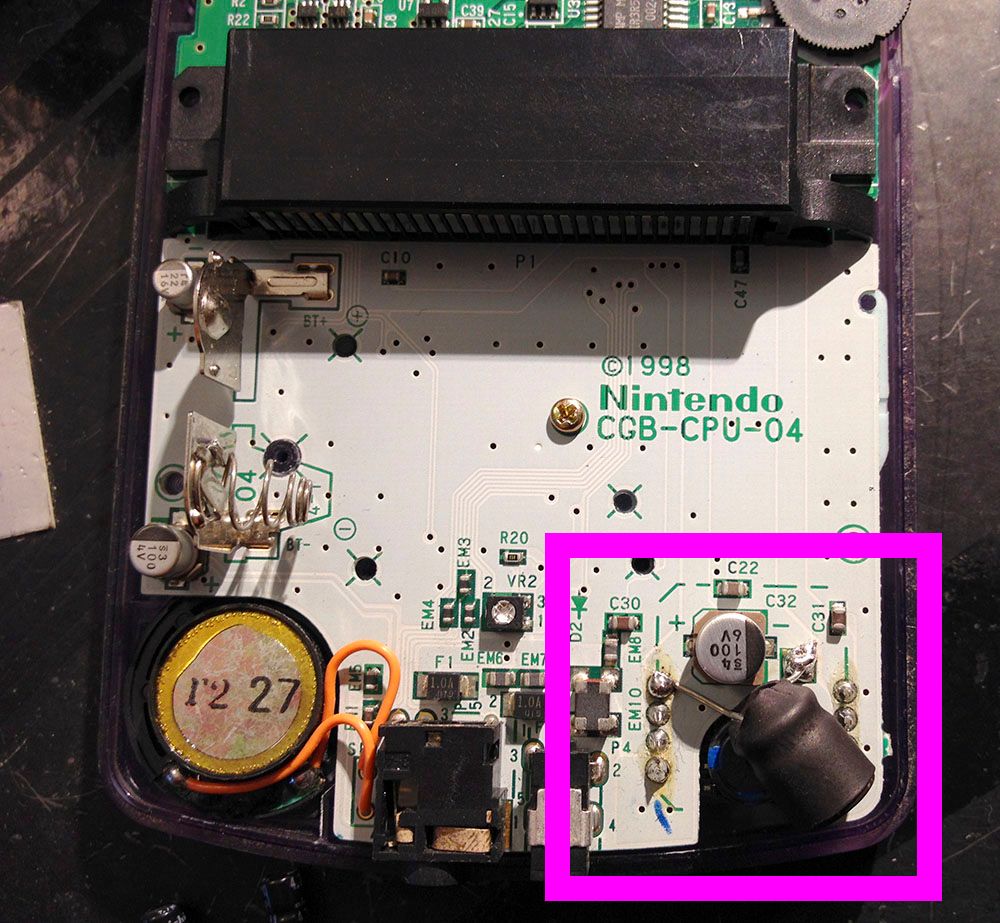
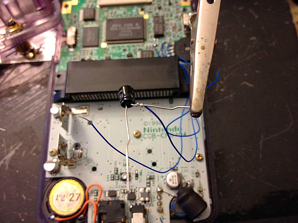
This is the area you will be working with for the noise filtering mod.
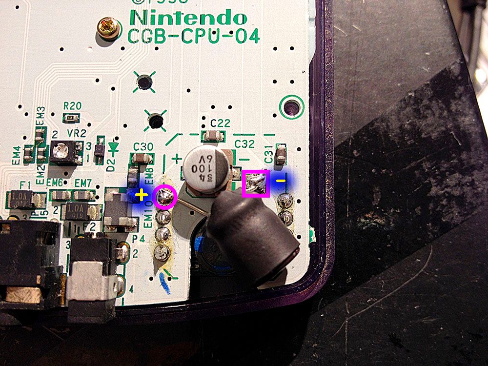
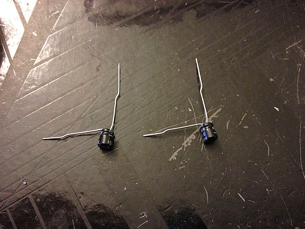
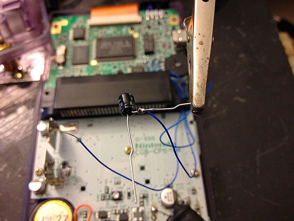
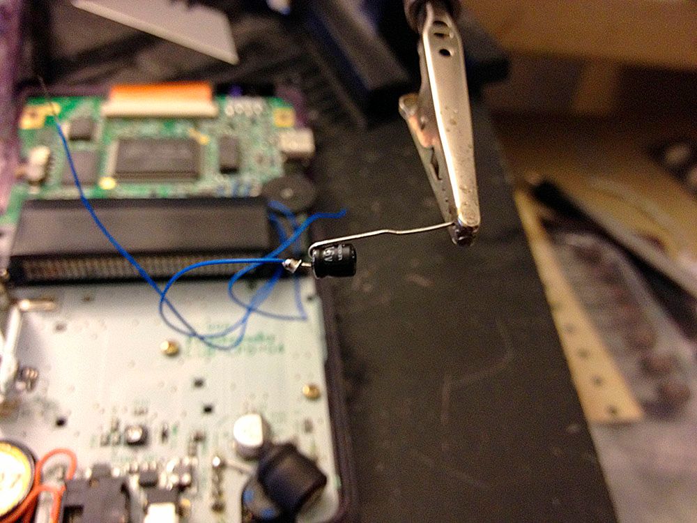
Take your 470UF capacitor and bend the legs and test fit in this area. The positive leg of the capacitor will go on the top post on the left while the negative leg will get soldered to the ground pad on the right side. You will have to heat up and add solder to the ground pad. After you are finished soldering, snip off the excess capacitor legs with diagonal cutters or nail clippers.

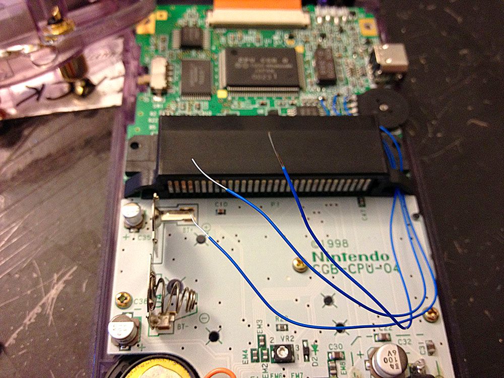
Cut three lengths of 30-gauge wire, roughly the length of the GBC, or a little longer than the length of the GBC.
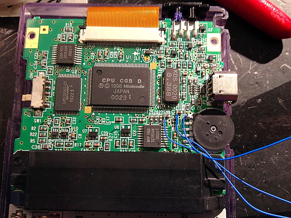
We will then need to strip the ends of the 30-gauge wire and solder them to the points we prepped on the GBC board for the bass mod.
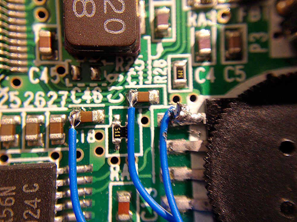
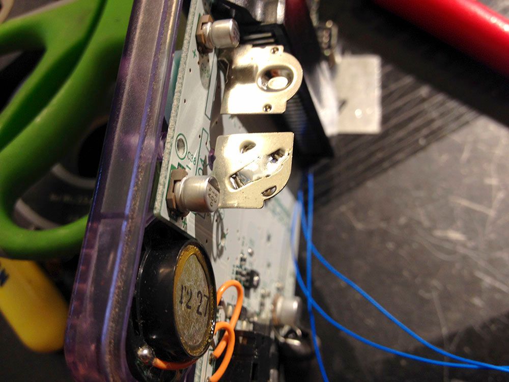
A close up of the wires soldered into place.
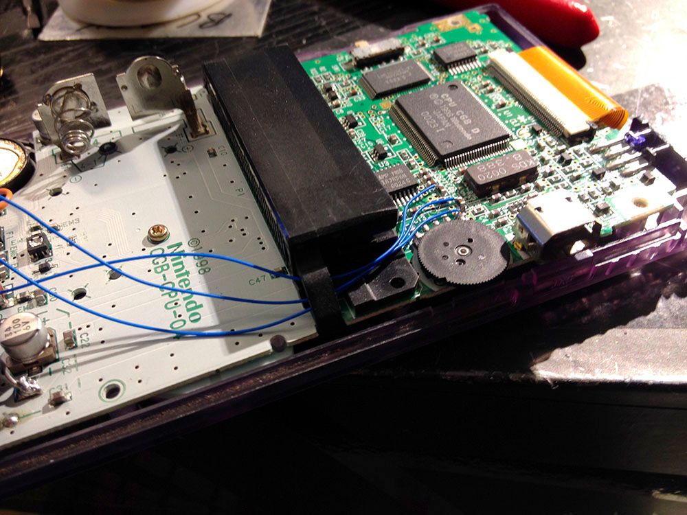
Next we will routing the wires through the right side of the cartridge connector in the gap between the cartridge connector clip and pcb.

Another shot of how the wires were routed.

At this time we will prep the battery tabs. We will be needing to remove battery tab from the rear case. You should be able to slip a small flat tip screw driver to push a tab to remove the battery tab.
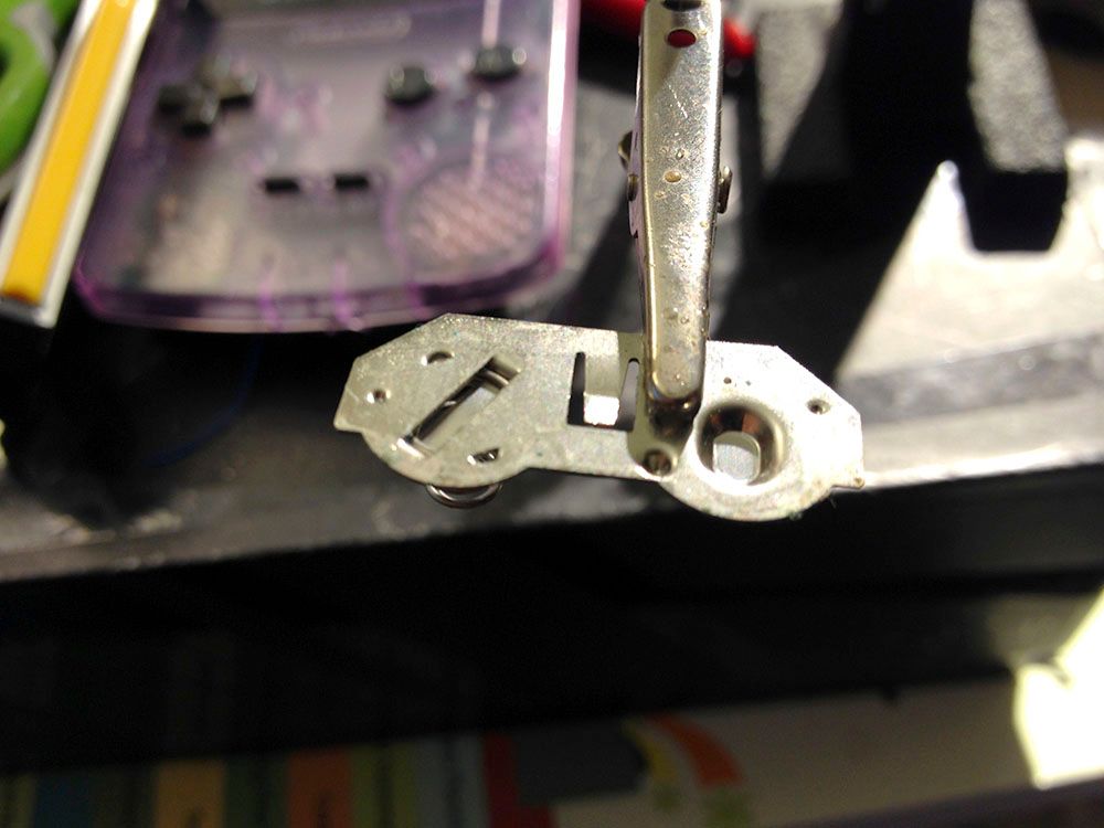
You will want to heat up the underside of the spring portion of the tab and flow solder through the gap. I do this mod to all the gameboys I mod. Whenever there are issues with batteries not making good contact in the battery compartments of gameboys, to what I have found, it is the contact between the spring and the battery tab. They are two separate pieces and the spring is crimped onto the tab. Corrosion tends to get between the tab and the spring, causing no continuity for current to flow.
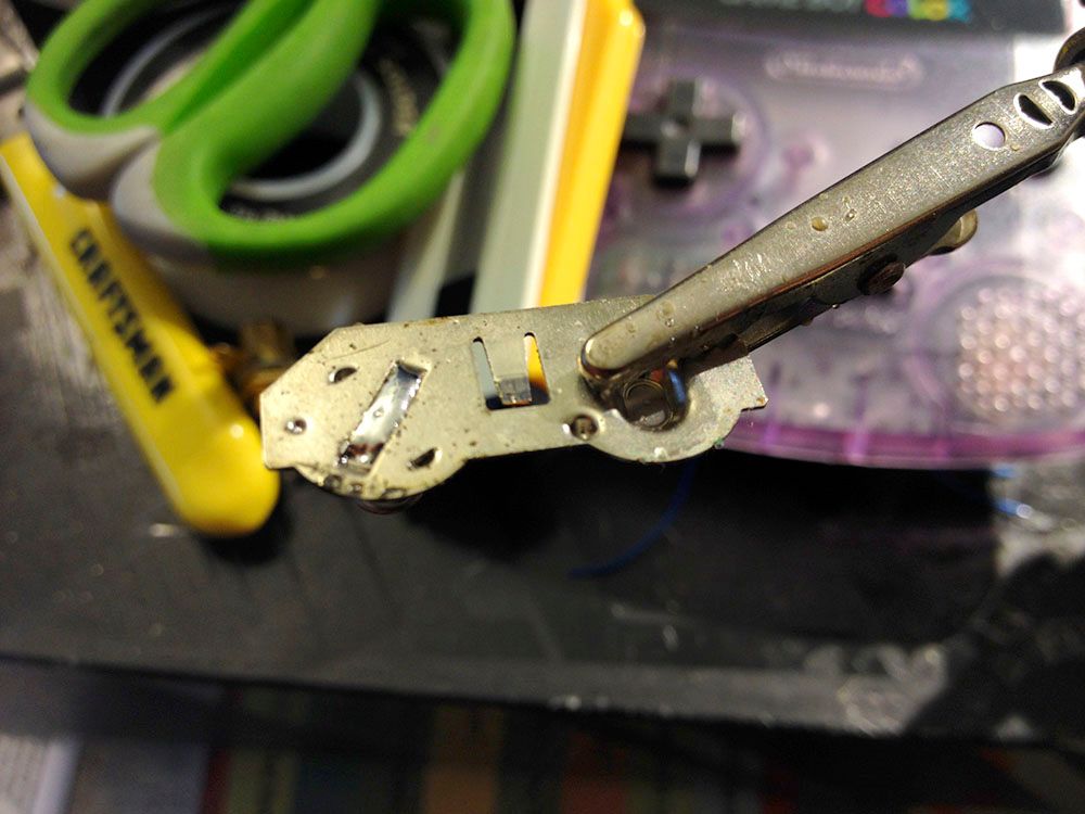
This is what the battery tab should look like after flowing solder through the gap under the spring tab. Reinstall the battery tab into the rear case of the GBC.
Do the same with the battery tab on the pcb.
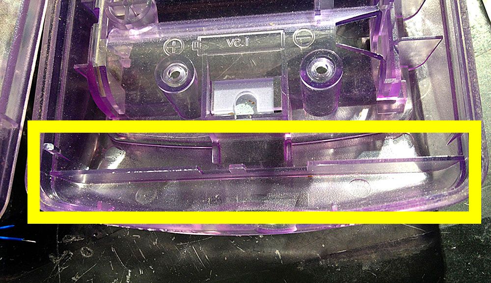
We will then trim away this plastic section from the rear case of the GBC using diagonal cutters.

This is what it should look like after you have removed the plastic section.
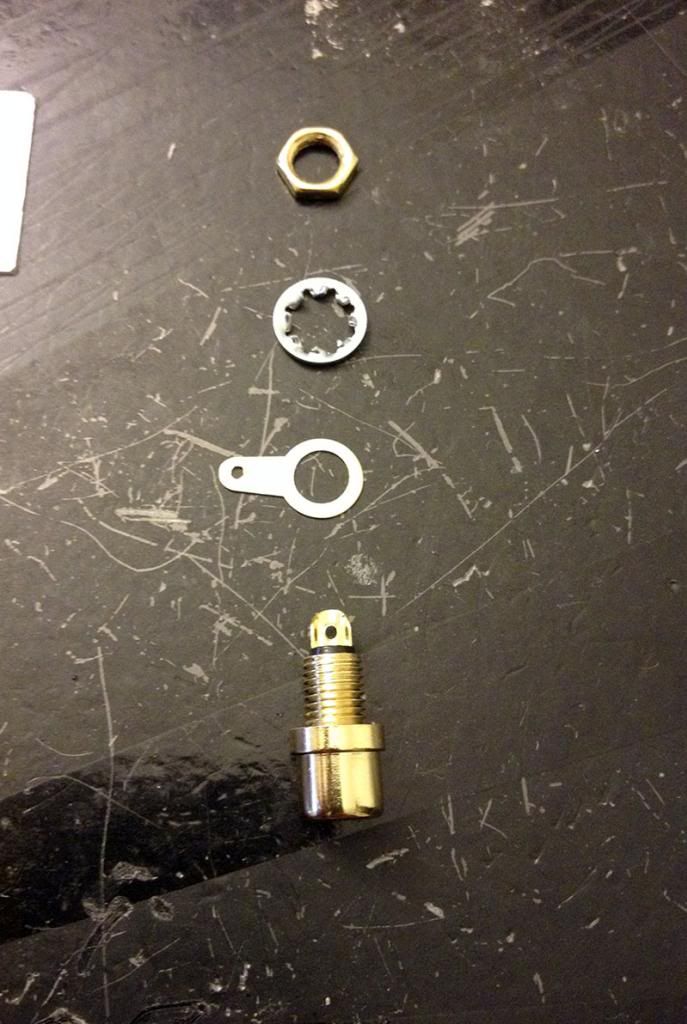
In this photo, I have the different parts of the RCA separated. I source internal star washers from a local hardware store, which I then use to help center where I want to drill holes into the case.
This is the area that we will be wanting to drill for the RCAs.
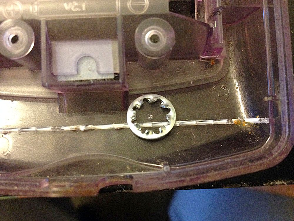
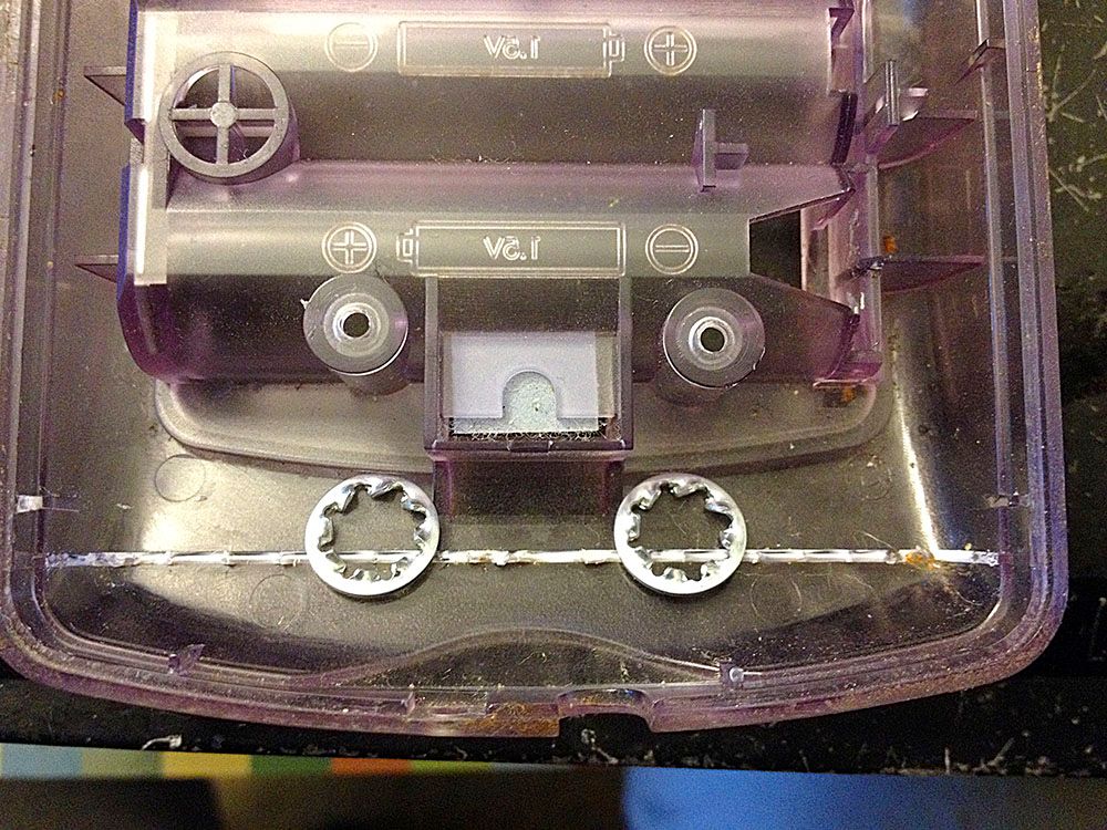
We want to place the star washer under the battery cover ledge molding and to the outside of the battery cover clip molding. Take a small drill bit and make a small pilot mark for where you will be drilling.
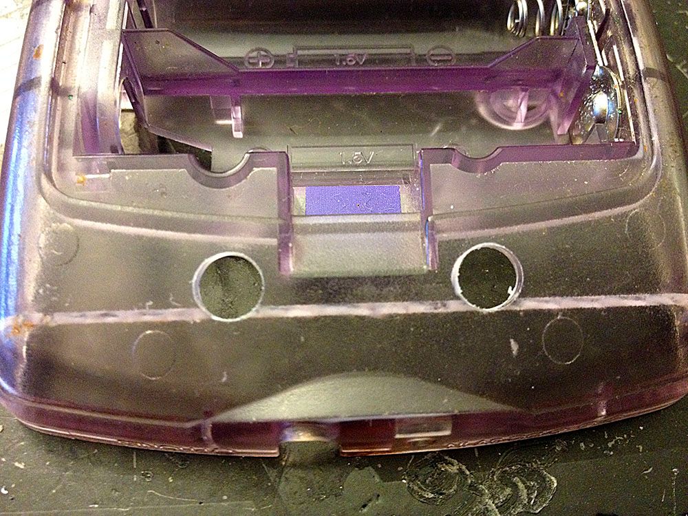
Working your way up, starting with small drill bits, use the smallest drill bit to drill out where you made your pilot holes in the inside of the rear case, then flip the case over and continue drilling with incrementally larger drill bits until [in my case] you finish off with a 1/4” diameter drill bit. This is what the case should look like when you are done. Please make sure to test fit your RCAs. Your RCAs may have a different diameter and may require a hole of a different diameter drilled.

Before we install the RCAs, we will need to shave off the tips.

Using a dremel with a grinding bit, you will want to shave off the ends of the RCAs to help give extra clearance from the PCB.
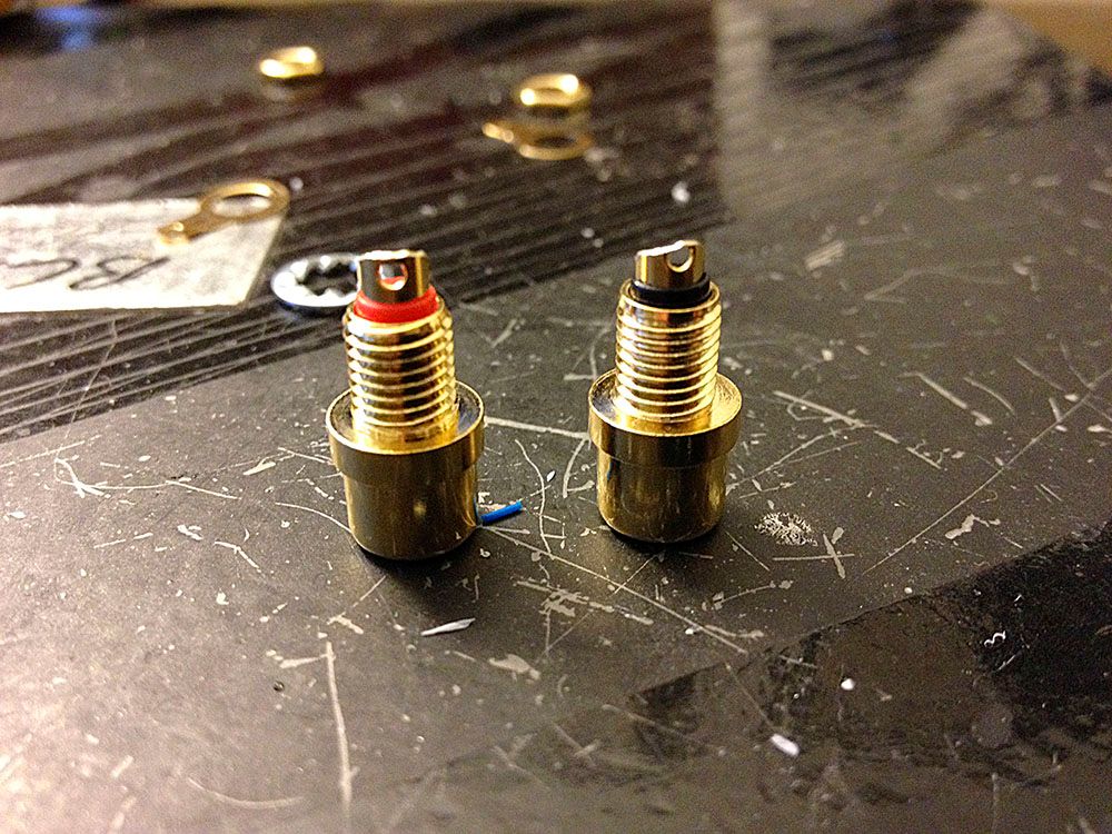
This is what the RCAs should look like, for the most part, once you are done shaving off the tips. Make sure to de-burr the RCAs with a razor blade if there are any shavings left on them.
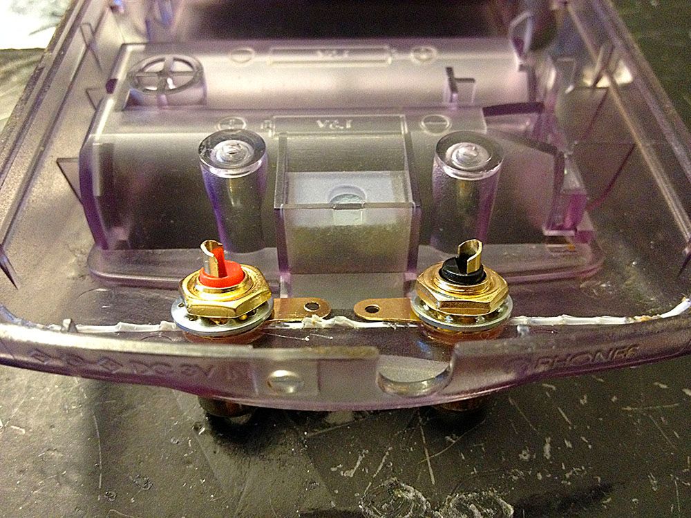
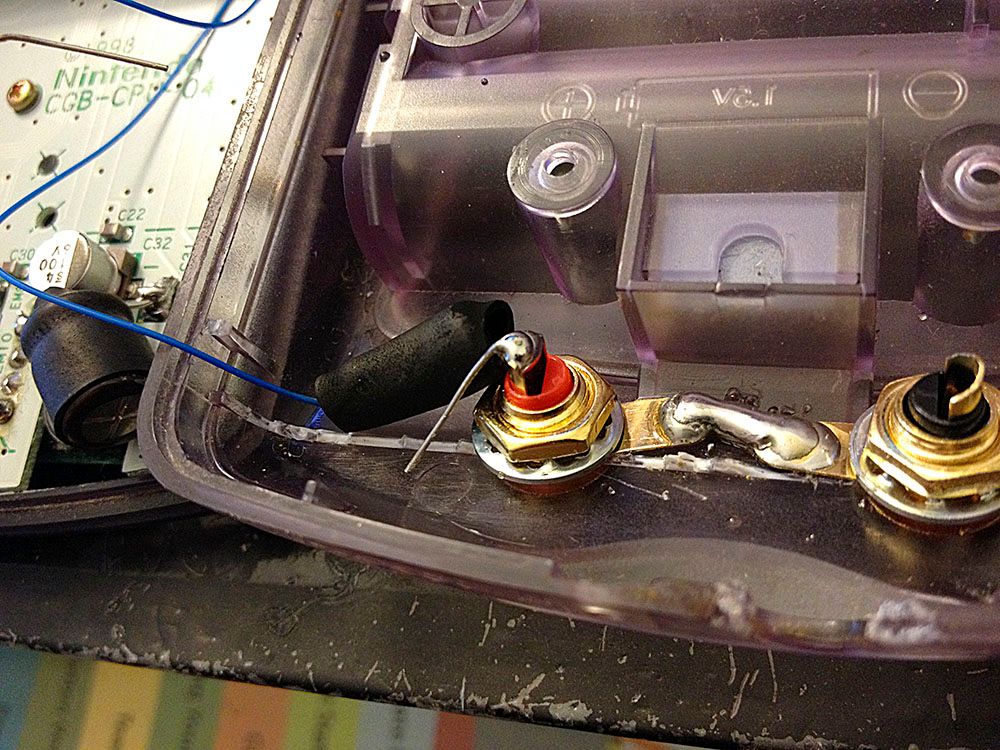
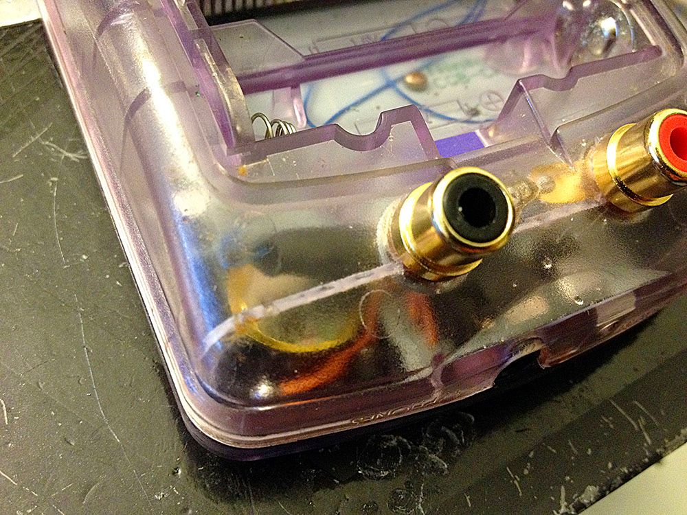
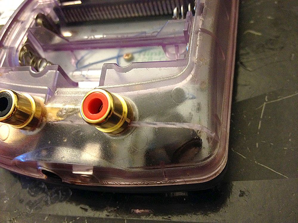
Install the RCAs with the RCA itself, the grounding tabs, star washers, and nut. Have the grounding tabs face each other and have the “crescent” portion of the RCAs facing outward, as shown in this photo. You don’t have to tighten the RCAs down all the way as we will be doing so in a few steps.
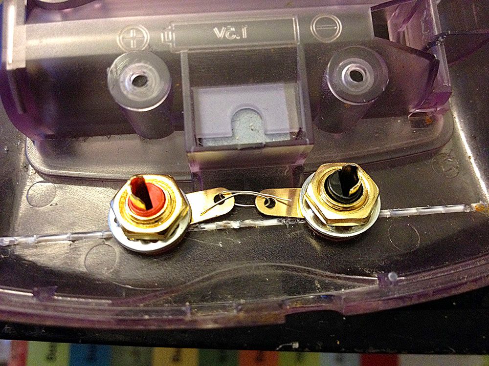
Strip a section of 30-gauge wire, snip it off, loop and wrap the wire in the grounding tabs.
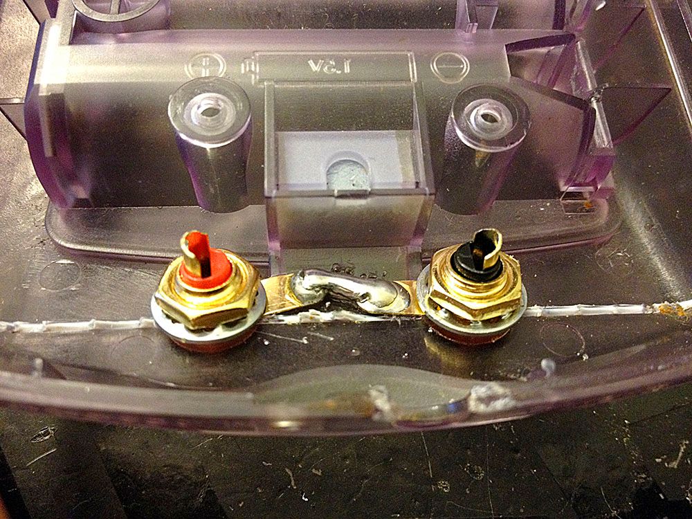
Flow solder between the two grounding tabs and wires. At this time, making sure that the RCAs are placed correctly, tighten the nuts down with needle nose pliers.
Strip the ends of the three wires that we soldered to the pcb earlier.
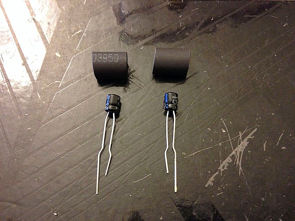
Next we will prepare the 4.7UF capacitors.
Bend the capacitor legs in an “L” shape.
Using the wire that is soldered to the left output on the pcb, wrap the exposed end of the wire onto the bent leg of the capacitor near its base.
Apply solder where the wire and capacitor leg meet. Snip off the excess material off the capacitor leg past the solder joint.
Bend the other leg of the capacitor around toward the top of the capacitor as pictured.

Cut two sections of shrink wrap that is long enough to both cover the soldered end of the capacitor and over the top of the capacitor itself. Slide it over the capacitor.
Apply the flame of a lighter, match or other heat source to the shrink wrap. Wait for it to cool down and slide over another section of shrink wrap over the same area and repeat the process of heating the shrink wrap. It should look similar to this after you are done. Repeat the same steps to prepare the second capacitor with the wire that is soldered to the right output on the pcb.

Once you are done preparing the capacitors, take the capacitor which is soldered to the wire for the right output, loop the exposed leg from the outside of the right RCA and wrap the leg over the top and to the outside of the RCA.
Solder the leg of the capacitor to the RCA as shown in this photo.
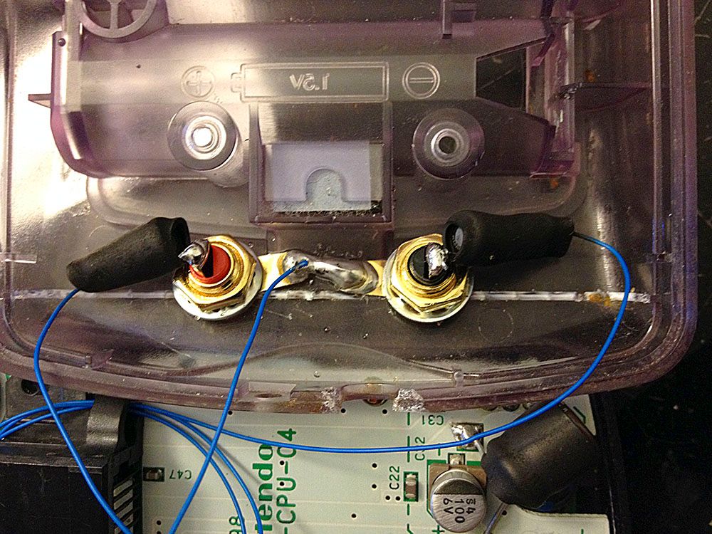
Repeat the previous steps to solder the capacitor which is soldered to the left output to the left RCA. At this time, solder the ground wire to the grounding tabs. Snip off any extra material from the legs of the capacitors at this time.
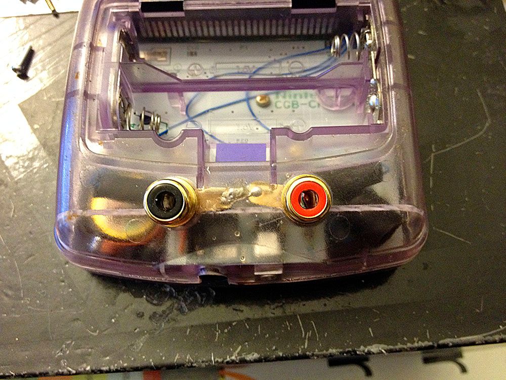
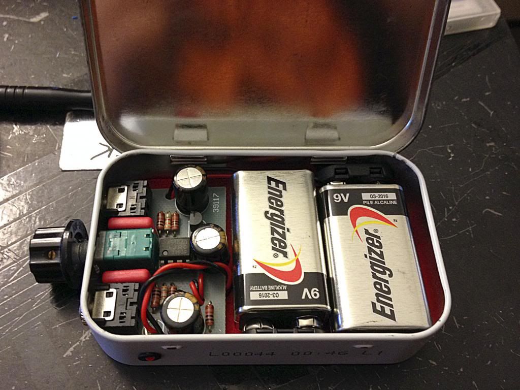
Close the Gameboy Color back up and you should be ready to rock! It will be a snug fit, but there shouldn't be any excessive resistance or pressure from the components to close the case securely. To test out the mod, I used my altoid tin headphone amp.
The output will be pre-potentiometer so if you want to adjust levels you will have to do so through a mixer or to whatever you are plugging your GBC into. There will be a definite boost in bass frequencies.
This mod will make the GBC a well desired gameboy unit for LSDJ. The GBC processor will be able to handle high tempos, handle complicated table commands and reproduce accurate samples in the WAV channel. The bass mod will bring up the bass frequencies and the noise filtering will take care of any hum or white noise. You will also use half the batteries as you would in a DMG.
I apologize for the quality of the photos. I used my iPhone 4s and edited the images in Photoshop. Hopefully this tutorial was informative and had enough photos to document the process accurately enough to be followed through.
A big shout out goes to Scannerboy who to my understanding was the first person to list this mod on this site.
You can bass mod with 1/4” stereo and 1/8” stereo as well. After sending Nonfinite photos of this tutorial he sent back photos of doing the bass mod with a 1/8” stereo jack using SMD/SMT capacitors.
If you have any questions, please feel free to message me or post in this thread.
***edit***
Corrected typo on capacitor value.
Last edited by katsumbhong (Jan 25, 2018 12:35 pm)