I can tell you exactly what's going on.

higher res
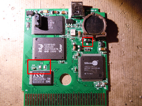
There are two red boxes in the image.
The upper right one is a diode array with two diodes in the same package. They both have the cathode connected to the bottom pin. The two upper pins are the anodes, ie where the voltage "enters" to speak simply. The right one of those is connected to the positive terminal of the battery and the right one to the 5V on the cartridge slot and USB supply. This way both the sources can power the SRAM chip without interfering. Otherwise, the +5V from the Gameboy/USB would destroy the battery and the battery would discharge through the other circuits on the board when there was no external power.
The chip marked ISSI is the SRAM chip. It's a really low power RAM module that will draw almost no current.
The other part of the magic secret sauce is the capacitor C12. It's there mainly to smooth out the power supply when turning on or off the external power. A capacitor is commonly compared to a bucket that can hold an electrical charge. When you turn on the external power, instead of going directly from ~3V from the battery to 5V, the power goes (relatively) slowly from one voltage level to the other. Same thing if you turn off the power. Instead of going right down to ~3V, the voltage slowly drops as the capacitor gets discharged.
Same thing applies even if there's no battery: the charge drops slowly from 5V to 0V as the SRAM circuit consumes current. Until the voltage goes below the threshold of what the SRAM circuit needs to hold the data, the data is retained.
This reminds me of something that happened to my mother. She discovered that the remote control to her TV worked for a short while after she had pulled out the batteries, and it also has a capacitor for similar reasons. She thought the remote control was magical/haunted.
