scienceguy8 wrote:


The one on the left depicts the way they were wired.  The one on the right shows how they should be wired.  Just switch the red and green wires on the MIDI out socket and everything will work just fine.  Don't switch the wires at the board, as this will mess with the color coordination (red=positive voltage, black=ground, green=data), but more importantly, unless you have a dedicated desoldering tool, you will not be able to get the wires back into the holes after you remove them.

PERFECT.

i'll do this tonight and report back. thank you.

just bought a mega memory card because of this thread. thanks!

thanks a lot man!

1,316

(1,485 replies, posted in Trading Post)

just bought some bits!

can you post a picture of the arduinoboy with arrows pointing towards the wires i have to switch?

1,318

(2 replies, posted in Trading Post)

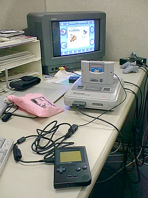
a midi-enabled super gameboy is a great idea.

herr_prof wrote:

I feel vindicated.

by what?

kvee wrote:

I feel like an idiot, because I remember actually seeing this tutorial smile
Anyways, you're welcome smile

between what you've posted here and this tutorial, i'll have no problem doing what i want to. excited!

akira^8GB wrote:

Usually you can remove these on any device without problem, since nobody in its right mind uses RF nowadays tongue

haha yeah, i was just wondering what i would do about the power/av outs. but that tutorial goes over all that.

i didn't know it was called an RF Box. a quick google search pulls up this tutorial -

http://www.instructables.com/id/How-to- … he-RF-Box/

SUCCESS! thank you so much!

kvee wrote:

RF box schematics:

(from http://www.neshq.com/hardgen)

wow, thank you!

kvee wrote:

Never tried that, but that box only contains a rectifier, A/V amplifier and RF unit, so it should be fine to desolder and put somewhere else. Just to be sure, use shielded wires for audio and video signals and regular ones for the power supply.
However, the casing also acts as cooling for the 7805 voltage regulator and can run really hot.
The "connecting points" connect the box to the silver framing (this is the system's ground) to enable shielding of the whole system (because the whole shield assembly also makes contact on this framing).

But as I said, I've never actually desoldered the box so it'd be nice if someone else can confirm what I just said...
The people at http://nesdev.parodius.com/bbs/index.php should be able to answer your question very precisely, they are the experts smile

awesome post, thanks for the response. i'll check those boards too.

i didn't realize that about the casing acting as the cooling for it or that the silver framing was the system's ground. thanks! very very helpful.

herr_prof wrote:

Im pretty sure the stereo mod bypasses this so you cna probably jsut cut it off. Check the ben heck forums for more stuff on potablizing your nes

http://forums.benheck.com/viewtopic.php?t=14764

well that little block also contains the power adapter stuff and the video output stuff so i couldn't just cut it off.

i did the stereo mod already though so the audio output will probably be ignored.

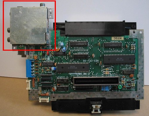
so, i want to take my nintendo apart and put it inside something else. the trick is, i want to cram a bunch of other stuff into it too and so, i need to make the best use of the space i have. i'd like to remove this piece and move it someplace else in the thing.

it looks like it's soldered to the board by 9 different points but i think only 5 of them actually do anything. the other 4 are just to physically connect the thing to the board. i don't know if i'm right about this or not.

so here's my question. can i just desolder these points and pull the thing off and then run wires from the board to that block at the points where it was connected? if so, what kinds of wire do i need? i really don't know a ton about this stuff so i'd appreciate any help i could get. thanks!

1,326

(20 replies, posted in Nintendo Handhelds)

imagine using the DMG-007 4 way connector and playing 4 super nintendos at once with 4 tvs!

4 lsdj's synced up with 4 tv's. insane.

1,327

(20 replies, posted in Nintendo Handhelds)

also, here's another tutorial.

http://www.mksmks.de/technical/sgblink.htm

1,328

(20 replies, posted in Nintendo Handhelds)

i'm going to be doing this mod soon and documenting it.

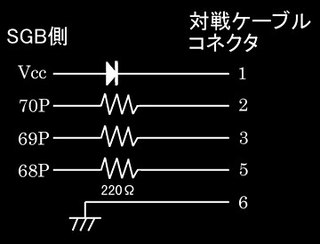
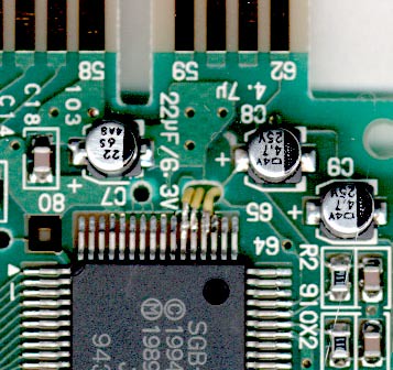
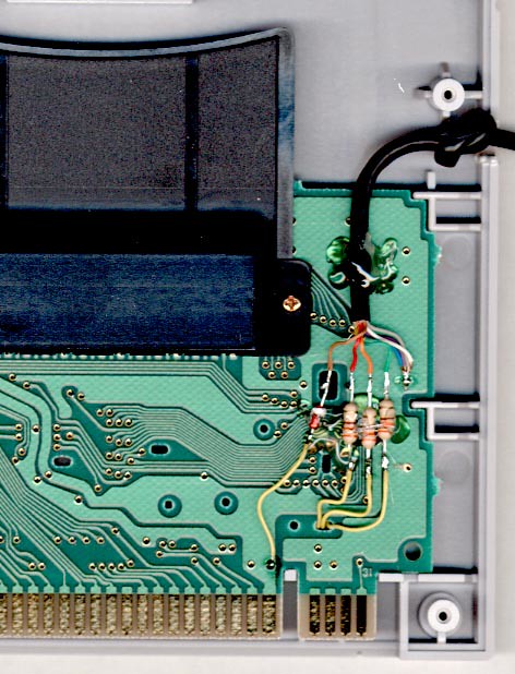
but for now, here are the pictures from the original japanese website that this tutorial ( http://www.devrs.com/gb/files/sgbmod.txt ) was based on.