^_^
1,266 Jan 10, 2010 10:06 pm
Re: Wanted: Dead DMG's and DMG-07's (39 replies, posted in Trading Post)
e-mail sent! Thanks man!
Hope things keep going this well!! Helps keeps the dead ones out of the landfill and the parts recycled for further projects!
1,267 Jan 10, 2010 9:38 pm
Topic: Wanted: Dead DMG's and DMG-07's (39 replies, posted in Trading Post)
I am in need of dead DMG's and or DMG-07's... I am recycling the power supplies, edge connectors and headphone assemblies...
The cases will also be recycled via an artist friend of mine (guess who!?)
Why do i want these? I am working on a new product that requires DMG link ports.
So if you happen to have a DMG that you killed via a display mod attempt, or purchased one that didn't work...
please PM me.. I can offer hardcopy releases from little bit records as payment. which one will be a surprise ![]()
Thank you very much in advance!
The PCB's i am in need of look like this:
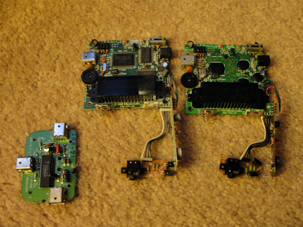
*image property of Thetris, all rights reserved*
1,268 Jan 10, 2010 9:26 pm
Topic: How-To: Convert your NROM-128 to an NROM-256 (0 replies, posted in Tutorials, Mods & How-To's)
How-To: Convert your NROM-128 to an NROM-256
by Low-Gain
Ever find it to be a pain in the ass to find the NROM-256 carts?
But have a bucket full of NROM-128's?
With just a few simple steps, you can make an NROM-128 into an NROM-256.
Modification Difficulty: Easy
Tools needed:
1 soldering iron
X-Acto Blade (or similar)
1 inch of 24awg wire or smaller
some soldering skills
Step 1: Look at the bottom of Both NROMs, 128 and 256 (if you have a 256 handy).
Note the similarities over all in part count, and lay out. There are 2 differences between the NROM-128 and the NROM-256, and they can easily go overlooked.
We're going to be looking at the solder side of the board (bottom). Focusing in on the PPG EPROM.
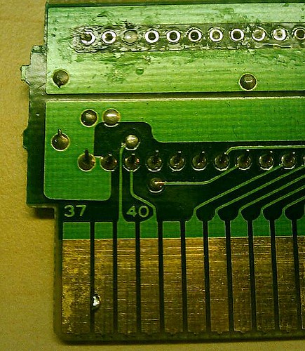
"nrom128 stock, note it lacks a trace going from pin 41 to Pin 27 on the PPG EPROM.
It is also connected to Pin 28 next to it which i believe is connected to the V+ Power plain which connects to Pin 37 on the edge connector. So that Pin is set to "high", we need to set it "low" by cutting the connects between pins 27 and 28 on the PPG EPROM"
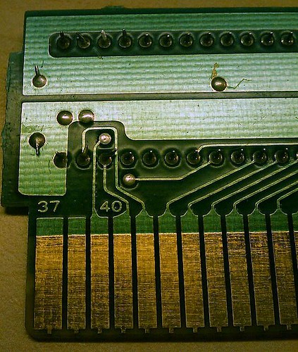
"N-Rom 256 Stock"
Step 2: Note Pin 27 and 28 on the PPG EPROM are shorted together. I believe this to be V+ which would be pulling that port High. Anyways.. we want to use an X-acto blade to isolate pin 27 from 28. thus setting that port back to Low.
Step 3: Scrape the small amount of solder mask covering the extra pin length of pin 41 on the edge connector portion of the pcb. This will be our pad for soldering the jumper. Once clear, tin the now exposed "pad".
Step 4: Solder a jumper from Pin 27 of the PPG EPROM to Pin 41 on the edge connector. it is easier to Solder the jumper to Pin 27 first. then wrap the jumper between the EPROM pins for a straight length (reducing risk of melting insulation off the wired when soldering) then soldering it to Pin 41.
You're Modification should look something like this: (my soldering is a little messy due to the fact that it's late and i never work well with an iron past 11:30pm)
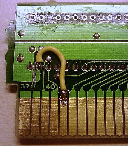
**Note: When making your jumper it's best to strip the insulation back a little more than needed on each end, tin the exposed wire, then trim back to a reasonable length. This will ensure a quick bond thus reducing the necessary head needed when soldering to the points of interest. **
As far as i know, that's all she wrote... I haven't had a chance to test this yet, but
i know this is what Alex Mauer does for his vegavox carts when needed. and it works. I just wanted to show ya that it's that easy and it makes life a lot easier
when looking for correct carts to use for burning your own EPROM's.
I will let Don (No Carrier) Explain the technical stuff since he's the wiz, not me.
For larger images, and a few more notes... visit the link below:
http://www.flickr.com/photos/lameboymus … 982863255/
Video and a better explained tutorial (more picture of steps) will be up soon on my website.
Good luck!
Post pictures of your success!
As usual.. let me know if there are any errors so that I may fix them. Thanks!
1,269 Jan 10, 2010 8:37 pm
Topic: Flier Request: (2 replies, posted in Graphics, Artwork & Design)
In need of a flier to be made within the next 2-4 days.. i have all the info ready, just lack the skills... I know it's last minute. >_<
Things just got crazy busy.
anyone willing to help out? Please PM me.
1,270 Jan 10, 2010 8:26 pm
Re: Off topic forum? (16 replies, posted in Bugs and Requests)
trash80 wrote:
Can someone explain to me the categorical difference between General Discussion and Off Topic?
Answer: nothing ![]()
1,271 Jan 10, 2010 7:54 pm
Topic: Ralp - Hydrioider (15 replies, posted in Releases)
Hydrioider. New release by Ralp for Spoomusic.

All of the tracks of these release are made only with one Game Boy DMG and the Nanoloop 1.3 program. Hydrioider album is a session in 45 tracks of almost one hour of music performed and recorded in live mode, with some improvised parts. It was recorded directly into computer with a Pro Sound modification in the Game Boy but without any extra effects, editions or postproduction stages. 100 % DMG and Nanoloop. Hydrioider was created during 2009. The cover is made with Photoshop.
Track list:
01 - Kuadrial
02 - Aescra
03 - Quidria
04 - Squepia
05 - Ecra Repruig
06 - Fredulix
07 - Ueard
08 - Krokork
09 - Flextor
10 - Fluxtion
11 - Turbot
12 - Sbadbla Putrielm
13 - Ufmeoh Yxial
14 - Codna ZF3
15 - Propescro
16 - Tuthmo
17 - Ventriculoid
18 - Leviol
19 - Sbuiltra
20 - Recrom
21 - Quecruad
22 - Bodrio
23 - Piodm
24 - Fibli Gblam
25 - Putrox
26 - Ruder
27 - Numbrah
28 - Prebraught
29 - Pedor
30 - Mermiol
31 - Sulfetarc
32 - Degradier
33 - Bubalstick
34 - Redreax
35 - Cosaco Pannot
36 - Kybernet
37 - Petrudex
38 - Hyrblock
39 - Huper
40 - Rupriert
41 - Shlamsh
42 - Trebliot
43 - Betafixt
44 - Metaclarp
45 - Kefda
1,272 Jan 10, 2010 6:57 pm
Topic: Old-school Low-Gain (17 replies, posted in General Discussion)
Figured i'd post these for the fun of it..
Back in the day when all this 8-bit, chipmusic, lo-fi stuff wasn't as hip as it is to day, and didn't have such cool names... we used to call it... "experimental"
lol..
anyways. during the ages of 14-19, aside from working on nanoloop and making really bad electronic music on various pieces of gear and the earliest versions of fruityloops, i used to perform live improv noise/ambient/sound-scape sets using children's toys/keyboards (mostly sk-1's and a casio SA-10) w/ FX, and loop pedals.
I have an album coming out in the next couple months from a more recent life performance that i think these will be a nice little sneak into the good old days of Low-Gain... (age 18-19)
1,273 Jan 10, 2010 6:49 pm
Re: Calendar (9 replies, posted in Bugs and Requests)
i believe a calendar is in the works.. as well as a member map. ![]()
1,274 Jan 10, 2010 6:46 pm
Topic: Output Mod on Super Game Boy (2 replies, posted in Tutorials, Mods & How-To's)
For non-commercial use only!
Enjoy!
1,275 Jan 10, 2010 6:42 pm
Topic: RCA outs on your Game Boy Color (1 replies, posted in Tutorials, Mods & How-To's)
**** NOTICE: IF INFO IS USED FOR PROFIT I WILL HUNT YOU DOWN****
Basically the how to is on my website, but here are the images of how to do it..
there are two circle indents on the inside of the gameboy colors back panel. i made my center punch for the hole at the bottom edge of this circle. Tightening the RCA jack nuts are a little tricky and i recommend using two needle nose pliers for that.
Be sure to deactivate the internal speaker as per my instructions on the "GB Color Line Output Mod" on my website. you can even remove the internal speaker after you remove the normalling resistor. it will give you more room for wire.
Note: I jumper the ground from one rca jack to the other... then ran all the wires under the pcb. this can be done with out removing the pcb. just be careful not to pinch any of the wires..
I used 24Gage wire.. i recommend it..
*click images for more detail*


1,276 Jan 10, 2010 5:26 pm
Topic: 1x3 Game Boy SyncBox Turorial (9 replies, posted in Tutorials, Mods & How-To's)
Convert your DMG-07 to a 1x3 Game Boy Sync Box.
I'll be adding this tutorial to my website but for now it comes to you in flickr format! ![]()
it's super easy and anyone should be able to do it.
i'll be doing a video for this asap.
enjoy!
http://www.flickr.com/photos/lameboymus … 419956111/
Add this + a GB Midi sync device and you have a lot of gameboys syncing up via midi! :-D
If you do this mod. please post your results here.. i'd love to hear stories of success..
And be sure to let me know if i didn't make anything clear.
thanks!
1,277 Jan 9, 2010 2:24 am
Re: Ghost Prosound MOd for GBC (8 replies, posted in Nintendo Handhelds)
1,278 Jan 8, 2010 9:20 pm
Re: LSDj echo tutorial (27 replies, posted in Nintendo Handhelds)
tRasH cAn maN wrote:
Another approach:
Screens showing instrument used to create delay effect.
Note that both phrases should be identical except for instruments.Using this approach you can set a delay value per tick. (Try increasing the H commands first digit for longer delay.)


\
another method in the tables is using a G00 in the tables... to slow the table down.. then use the O command to "slice" the sound w/ a longer decay to give the sound of echo.. it works nice.
1,279 Jan 8, 2010 7:55 pm
Re: Apple II Music (26 replies, posted in Other Vintage Computers & Consoles)
I is still waiting to find a IIgs Color monitor.. any luck Tony?
I need to get my Atari running too... so much to do... so little time.
1,280 Jan 8, 2010 7:06 pm
Re: Mixing/Master LSDJ Tracks? (52 replies, posted in Audio Production)
I do mastering myself, but with my backlog for the record label as it is.. i'm just not available ATM.
and when i say "mastering" i say that loosely... i can balance tracks out to the best of my ability, make it pop/loud/radio friendly... and set tracks spacing, but i dont consider myself a professional mastering engineer. Takes magical ears for that which i have probably lost due to too many gigs w/o ear plugs. But for chipmusic.... Most wont hear the difference anyways. hahaha