49

(1,206 replies, posted in Nintendo Handhelds)

ok.. this took me the whole friday and i almost went nuts, but i did it...

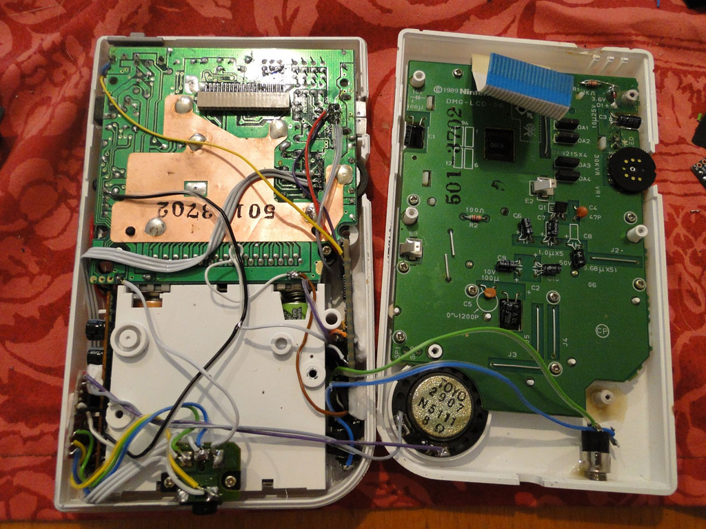
on the left side is the amplifier board and on the right side the arduinoboy
it didnt work and i resoldered and changed parts (i tried 3 different arduinos) a thousand times, and almost smashed it, but then i found out what was the problem...
the cheap arduino pro mini from ebay didnt support 1.2.3 arduinoboy (or arduino 1.0 software language), so i downloaded arduinoboy 1.2.2 and used one of the older alpha arduino softwares and finally finished my midiboy.

be sure to check out the short vid on my blog

50

(1,206 replies, posted in Nintendo Handhelds)

I got my mini amplifier boards today and could not resist to put one in my beloved white dmg. i uploaded a short comparison on youtube to let you see the difference. you cant really hear how lout it really gets on youtube, but its really really loud big_smile

Watch the Video Comparison

51

(1,206 replies, posted in Nintendo Handhelds)

today i painted the kitsch bent case red on the inside, it didnt respont very well to the paint, but i am still happy with the results. i will change the backlight and led to a more caressing colour soon.
also on the right you can see my new project (the megaman gameboy). still waiting for buttons but you might get the idea already.

I dont know for keyboard, but on midi clock the lights will light up no matter if a GB is connected.. so i guess the same goes for keyboard!
I know many people who think they wired everything correct, be careful on the schematic, some things arent 100 % clear!
i never had 2 broken LED's at once, this is very unlikely if 2 out of 6 dont work. I guess you have something wired up wrong.
Double check the wiring and after that, repeat the process big_smile

53

(1,206 replies, posted in Nintendo Handhelds)

Hey Boddah!
Yeah the black one is an inside painted clear boy with clear finish. I like them too, but the real beast will be unleashed soon, i am building something special at the moment. something like my old orange dmg (see blog).

I also finished my arduinoboy #3

there is also a video on my blog

I am still waiting for my GB Link cable to test it out properly big_smile

you got the Pins wrong, this is what happens when you switch the pins of the GB Link Cable.
The Pins on the Schematic are from the cable (looking at the cable). Also look if you got the Midi Port Pins right (if it synced before you got them right already i guess).
Check if you have wired everything right (check newest schematic).
http://trash80.com/arduinoboy/arduinobo … _1_1_0.png

Also which Arduino are you using at the moment ?

sounds like a pin swapping problem to me. Also check that you have got no shorts to ground and recheck everything.
pics would be helpful..

55

(1,206 replies, posted in Nintendo Handhelds)

Thanks... i changed the silicone buttons to white for a better match yesterday.. hope you still like it..

i am currently working on arduinoboy #3 in white so that it matches my dmg big_smile

56

(1,206 replies, posted in Nintendo Handhelds)

kitsch-bent clear case in retro look

57

(1,206 replies, posted in Nintendo Handhelds)

for those not following my blog

i currently build 3 arduinoboys... 2 are finished

and i changed design of my two current dmg's

peace

58

(33 replies, posted in Nintendo Handhelds)

Hey all.

I just finished to build a Arduino Pro Mini Arduinoboy.
It worked on the first try.. so i guess the problems above were all only arduino mega problems, will post pics of my second boy soon smile
lovin it'

Note: Midi Out doesnt work on Arduino Mega 1280 (even with modified code). It works perfect on Arduino Pro Mini, so i will in the future only use Arduino Pro Minis or Nanos.

59

(33 replies, posted in Nintendo Handhelds)

Ok i did it... it works now... just still freezes randomly.. i will upload the Arduino Mega Version somewhere, maybe it is helpful for others ?
I recoded the PORTF PINF Commands, and also corrected the DDRC -> DDRF.
in the int assign i used A0,A1,A2.
It works now and can be used with your schematic. Finally.. i feel so relieved big_smile

Thanks Trash!!


PS: OK I DONT GET IT... NOW ITS ONLY FREEZING and will not work again, i didnt change anything from the working state before.. what the heck is going on

PS2: Now its working again, i think its some kind of weird undefinable thing, its now AM 2:20 in the morning here.. i think i will catch some sleep, at least its working now (partially) on the next build i will not use a Mega Board anymore wink

Here is a short video uploaded: http://chipmod.blogspot.co.at/2012/07/n … k-boy.html

60

(33 replies, posted in Nintendo Handhelds)

yeah but i read 4,83 Volts on the Clock Pin, the Data Input and the Data Output Pin to Ground. Is that normal ?
I wired exactly like stated in the shematic. i saw it working once so i am motivated again, just cant figure out why i have 4,83 Volts coming from the gameboy (i checked another gameboy too) to Clock / Data Out / Data In..?!

61

(33 replies, posted in Nintendo Handhelds)

Hey.. i had some luck with changing the "int pinGB etc.." port assign to 37,36,35 and reconnecting the wires.
the gameboy started with the midi signal and seemed like it was in sync (at least near).
The only strange thing is that the Status LED wont flash no more to the beat (it only stays lit)
And after one full modeswitch (approx. 6-7 button presses) the arduinoboy will crash.

I measured the pins on the GB Link Cable.
The Pin 0,1,2 all have 4,83 Volts to Ground. Is that common ?
I found out that the arduinoboy only crashes when the GB Link cable is connect, also LSDJ crashes and comes up with an error message.
You said that it should be Serial + / Serial - / GB Clock / Ground.
But how come i have 4,83 on Serial + / Serial - and GB Clock to ground ?!
somethings wrong xD

62

(33 replies, posted in Nintendo Handhelds)

Thanks Trash for your time,
i tried to replace all the PINC/PORTC with PINF/PORTF
It didnt quite work out.. do i have to change the int pinGB**** etc.... Stuff also if i switch to 37,36,35 ?
I tried to switch the pins but the Arduinoboy went crazy.
But the Gameboy started his sync when i pressed the pushbutton once (and never stopped again)
Something must be completely wrong.
I will build another device with an Arduino Pro Mini and see what this one does...
Maybe any other hints ?
Thanks again

63

(33 replies, posted in Nintendo Handhelds)

Thanks guys, but one question.. i tried to wire up the gameboy to my arduinoboy.
in the schematic it says GB Cable and you see the pins. i soldered it that way but in LSDJ it just keeps waiting and doesnt start at all.
Has the GB Cable to be wired this way going to the Arduino, or is the pinout going to the Gameboy ?
I dont understand why it doesnt work...

PS: I tried both methods. The Difference from the Cable to the Gameboy / Arduinoboy is just 2 Pins (Analog in PIN2/PIN1 switches around).
It seems that nothing works, the Arduinoboy responds to my MidiClock that i send with cubase, but the gameboy doesnt.
I wonder if it has something to do with the Analog INs ?! (i dont really get it how Analog Inputs can send the gameboy a signal)
It could also be my Arduino Mega 1280 (chinese copy) ?!
Maybe someone has a clue. Thanks guys

64

(33 replies, posted in Nintendo Handhelds)

First test of my arduinoboy #1 big_smile ... http://chipmod.blogspot.co.at/2012/07/a … -test.html