Offline
A gray world of dread

Not sure if this is the proper section, mods feel free to move this if not.

I'm interested in the cause of some of the 'dirt' on chip waveforms. You never have a perfect square, and I'd like to know the reason for some of the aspects.

Let's start with this DMG wave (lifted from H.Weixelbaum's page):

The squares don't have a flat top, but fall off. My guess would be a decharging capacitor? There are also spikes on the voltage flips, how are these caused?

Atari 2600 (nicked from litte-scale):

Relatively flat tops- what's different to the DMG? There's also what looks like resonance on the square peaks. Are these from a crystal?

I'm not so much looking for the math behind it (although that'd be nice too), but more for which parts of hadware cause these effects.

Last edited by µB (Feb 23, 2010 5:16 pm)

Offline
Carbondale, IL

I love this question!  I've been learning some of this in my Digital and Analog Communications class.

This is a perfect example of what is called the Gibbs phenomenon.  It's what happens when a square wave is passed through a low-pass filter.
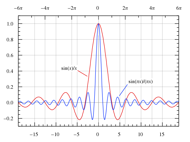
In the above picture, we see the waveforms of two low-pass filters.  Any signal that falls underneath the large peak at the center of the graph is allowed through.  Ideally, no other wave component is allowed to pass, that is all waves that fall outside the central peak are filtered out.  However, you can see where the low-pass filter still exists outside the main filtering frequency.  Higher frequencies that we want filtered out are still slipping past, generating the diminishing sine wave you see at the top and bottom of the square wave.  As we make the low-pass filter narrower, the Gibbs phenomenon also gets smaller, but can never be made to disappear.

Basically, it's a technical limitation and a fact of life that really has no effect on you unless for some bizarre reason you need a completely clean square wave.

You can also see the Gibbs phenomenon in your DMG square wave there.  Notice how the wave seems to extend beyond it's logical point and ripples ever so slightly before settling back down into the primary wave?  The DMG square wave appears to be on a very narrow low-pass filter, resulting in a very small Gibbs phenomenon.

EDIT: additionally, the Gibbs phenomenon can be seen in the generation of square waves themselves.  You can generate a square wave by combining multiple sine waves together, with the result being a square wave exhibiting the Gibbs phenomenon.  The greater the number of harmonics (the number of sine waves you are combining), the smaller the Gibbs phenomenon.  If you want, I can try to teach you the math, but I'm afraid I barely understand it myself.

Last edited by scienceguy8 (Feb 23, 2010 4:46 pm)

Offline
A gray world of dread

Wait, I've seen this before. That is, if you synthesize a square with additive synthesis using Fourier Transformation. I'm confused now. If you low-pass a square, it becomes more and more sine-like, doesn't it? I.e. the reverse effect of what you get by adding the harmonics on a sine to get a square.
The waves of these systems are in digital nature though (ie the basis is a square, not a sine), so I don't see how this could be a Gibbs effect.

Edit: Right, I'm and idiot. Of course the effect would appear if you low-pass a square, based on what I just said. Thanks!

I didn't know they put low-pass filters in, that's interesting. Why would they bother?

Edit edit: Probably to reduce the hiss. I love answering my own questions 5 minutes later, makes me look like a lazy ass.

Last edited by µB (Feb 23, 2010 5:18 pm)

Offline
York, Yorkshire
µB wrote:

I love answering my own questions 5 minutes later, makes me look like a lazy ass.

Or like you posted so you can show off tongue

Offline
A gray world of dread

Haha yeah, like Plato. I'm still interested in that fall-off on the DMG square, if anybody knows.

Oh, and also some effects of crosstalk. I realize this depends on the circuit, but if there are common ones it'd be nice to know.

Last edited by µB (Feb 24, 2010 8:30 pm)

Offline
nz

Awesome thread!  Thanks Scienceguy for the info.

µB wrote:

Let's start with this DMG wave (lifted from H.Weixelbaum's page):

The squares don't have a flat top, but fall off. My guess would be a decharging capacitor? There are also spikes on the voltage flips, how are these caused?

I have a limited understanding of the math and physics involved but I've seen this waveform in some of my DIY stuff.  That kind of falloff does look like some kind of capacitor discharge at or near the output or something to do with load at the output, maybe even the speaker is bringing it down.  They're calling it Low Frequency Roll off.

Maybe changing the speaker would change the wavform, that's an interesting idea...

Some links that might shed some light:
http://www.machrone.net/mt/archives/202 … phs_a.html
http://commons.wikimedia.org/wiki/File: … charge.svg
Figure 10 @ http://www.eal.gr/english_language.htm
http://users.tpg.com.au/users/ldbutler/Waveforms.htm
http://ap.com/kb/show/187
http://diyaudioprojects.com/Tubes/6T9-Tube-Amp-Kit/

I think Low Frequency Roll Off is a great name for an album, hehe.

Last edited by droffset (Feb 24, 2010 8:57 pm)

Offline
Central-ish VA

Thank you so much scienceguy8, this has never been something I've needed to know, but damn that was interesting like you wouldn't believe!

Offline
A gray world of dread
droffset wrote:

I have a limited understanding of the math and physics involved but I've seen this waveform in some of my DIY stuff.  That kind of falloff does look like some kind of capacitor discharge at or near the output or something to do with load at the output, maybe even the speaker is bringing it down.  They're calling it Low Frequency Roll off.

Maybe changing the speaker would change the wavform, that's an interesting idea...

Ahhh, impedance. I haven't considered this. Unfortunately I remember next to nothing about it, I'll have to read up. Thanks for the tip!

Good summary here

Last edited by µB (Feb 24, 2010 9:51 pm)

Offline
ad-hell-aide

Great thread!

Offline
A gray world of dread

Short discussion of the above on IRC, kudos to abrasive for explaining:

<uB> so the shape of the waveform would change with frequency
<abrasive> the exponential decay curve should stay the same
<uB> absolute or relative to the duty cycle?
<abrasive> absolute
<abrasive> its time constant will be set by physical components
<abrasive> i expect that is the DC blocking capacitor
<abrasive> -> high pass filter
<abrasive> so the fast edges are preserved
<abrasive> but the bits that should be flat are not
<uB> cool, I wasn't too far off then
<uB> thanks!
<abrasive> headphone/other loading on the output will change things, how much and in what way depends on the dmg output arrangement.
<uB> there are some ciruits to dynamicaly adjust this, right?
<abrasive> to adjust the loading you present to the DMG?
<uB> welllll, the output impedance
<abrasive> that's... complicated.
<abrasive> you can adjust the input impedance of whatever you plug into the dmg easily enough
<uB> I'm not trying to mod anything, I just needed the details for some pet project of mine :)
<abrasive> a headphone amplifier typically has high impedance (10kOhm and up)
<abrasive> you can then put resistors across the dmg output to reduce the impedance seen by the DMG
<abrasive> and the output waveforms will change.
<uB> hm, you could bass it up that way
<abrasive> this is part of the reason for pro sound mods - you bypass the output HPF, and get better bass
<abrasive> but since there's also no amplifier you can't drive low impedance (headphone) loads with a prosound out.
<abrasive> i think the DMG internals go audio out -> amplifier -> HPF -> jack
<uB> shouldn't there be a LPF that causes the gibbs effects on the waveform, too?
<abrasive> inherent in the circuitry
<abrasive> parasitic effects
<uB> ah
<Scotty> why isn't the audio amp first in the cirsuit
<abrasive> the HPF blocks DC out from the amp
Offline
nz

Thanks that makes a lot of sense.  It's common advice among DIYers to place that capacitor in the output of audio circuits.

I'm wondering why the prosound mod would bypass the amp then?  why not just cut the trace for the HPF and wire it directly to the jack?  (I haven't looked at the mod instructions more than once though.)

There are some good simple bass boost circuits out there by the way.