Offline
Melbourne, Australia

I mentioned this here:

http://chipmusic.org/forums/post/189085/#p189085

And now I've finally gotten around to writing the code to get it off the ground, so here is some information and some demonstration:

FamiiDI: MIDI Input & Wii Nunchuk arduino shield for the NES / Famicom


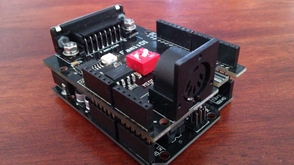
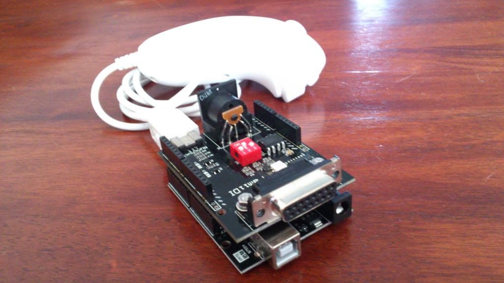
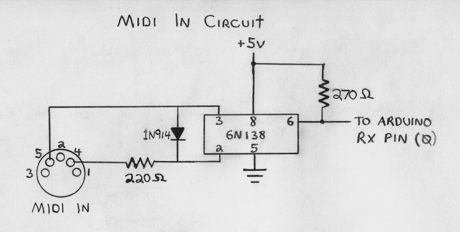
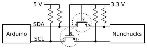
FamiiDI (Famicom / Wii Nunchuk / MIDI) is an Arduino shield that reads in data from a MIDI serial connection, or a Wii Nunchuk controller, and translates that data to the 15-pin 'Famicom Expansion Port' standard.

All of the 15-pin Famicom Expansion Port signals are also present on the 48-pin NES Expansion Port that lurks hidden on the console's underside - and there is a great little device called the 'ENIO EXP Board' that acts as a 48-pin to 15-pin converter if you don't like the idea of soldering directly to the NES motherboard (or cutting the cable off a joypad to build your own 15-pin to 7-pin cable to connect directly to the NES Controller Port).

The FamiiDI shield appears to the NES as a joypad connected to Controller Port 2, so you can still have a regular joypad connected to Controller Port 1 without any conflicts. Demonstration # 1 in the video shows a MIDI sequence being played from a laptop into the FamiiDI board. The Arduino then maps the MIDI Note On / Off data received (note numbers 59-66, or B3-F#4) to each of the eight joypad buttons (A, B, Select, Start, Up, Down, Left, Right) the NES is running a Controller Test ROM which plays a different musical pitch for each button pressed.

The video also demonstrates sending a proportional analog input (rather than just digital on / off button presses) to emulate an Arkanoid Paddle by taking an 8-bit value (0-255) and mapping each of the 8 bits to the eight button presses read in by the NES input register at $4017.0 (a separate on / off value for the Paddle Button is sent to input register $4016.1).

PS. The 15-pin Expansion Port standard also means there is the potential to map another four Note On / Off signals, so rather than just eight notes (only the white piano keys) you could send a full twelve notes (both the black and white keys). The four additional pins present on the FamiiDI shield are:

$4016.1 (traditionally used for the Arkanoid Paddle Button)
$4017.1
$4017.3 (traditionally used for the Zapper Gun Light Sensor)
$4017.4 (traditionally used for the Zapper Gun Trigger)

PPS. Because of the potential for so many 'modes' I've also put 3 dip switches on board to allow for code that reads the state of the switches and changes mode accordingly, and there is also an RGB LED on board wired directly to the dip switches for quick and easy representation of the selected mode by color:

(0. 000, Off)
1. 001, Green
2. 010, Blue
3. 011, Blue + Green = Cyan
4. 100, Red
5. 101, Red + Green = Yellow
6. 110, Red + Blue = Pink
7. 111, Red + Blue + Green = White

Last edited by uXe (Dec 20, 2013 12:11 am)

Offline
Dallas, Texas

This looks so cool. So it is essentially converting midi data into button-press data?

Offline
Melbourne, Australia
TylerBarnes wrote:

This looks so cool. So it is essentially converting midi data into button-press data?

Yep! (that is not all it can do though)

MCTRL does the same thing:

http://www.ninstrument.com/?page_id=783

Offline
Dallas, Texas

Thats pretty neat. Would be interesting to see if someone tries to use it to sequence gameplay of some video games. Kinda like recording a perfect speedrun without savestates and other such tool assists.

Offline

Awesome!  Neil is working on doing more with this type of sync with his music titles.  He gave me an early release that allows you to control the step sequencer in PR8.  It also will allow pattern change as well as reset.  Keep up the great work!  More info soon.

Offline
Milwaukee, WI

Bump because people are literally talking about shit on the front page.

Offline
SLC, UT

Awesome dude! Any immediate plans to release the source?

Offline
Arizona

Very cool things going on here.

Offline
Melbourne, Australia
stargazer wrote:

Awesome dude! Any immediate plans to release the source?

Thanks! The source is pretty straight-forward, but it is written to work specifically with the shield - if you are just interested in the MIDI side of the project, and wanted to build it yourself quick and dirty, I could send you a cut-down version of the source and you would just need to build the standard Arduino 'MIDI IN' circuit, like this:

and then open up a NES joypad and connect the 8 input pins on the joypad's shift register to 8 pins on the Arduino and you'd have yourself a MIDI controlled NES joypad! smile You would even have enough spare pins to connect another 8 to a second joypad if you really wanted to...

I should mention, with the Arkanoid Paddle emulation stuff it is either / or, you can't be using the Arduino to emulate paddle position and a joypad on the same shift register at the same time because they both want to be in control of the shift register!

Offline
SLC, UT

Sweet, any plans to sell the shields? I have to say that thing looks pretty intense. And I'd love to just throw it right into my NES with a switch that would switch it back and forth from regular joypad. I'd probably be mostly interested in the basic circuit though, however depending on price I'd also be interested.

If I read your circuit correctly you'd need an external power supply for this?

Lastly, what specific Arduino are you using there? If I'm going to build a dedicated interface, what would you recommend for a cheap, preferably small arduino? I know Batsly Adams was using the rBBB. (Side note, check out his blog post from today, way intriguing!)

Thanks again man! Great work!

Offline
Jelly Stone park, MD USA

Very nice! looking forward to seeing the sketch. Setup on a Teensy, it would make a compact midi/sync interface. Could even fit it into a game pad!
Yogi

Offline
Melbourne, Australia

I would be happy to have a batch of these shields made if there is enough interest - I'll keep a list of interested people, and if the list gets long enough then we can go ahead and put in an order! From what I've been told they should only cost about $8 each to produce...

The 5V and Ground connections in that circuit I linked to could just be connected to the Arduino's 5V and Ground pins, but yes the Arduino would need a power supply. I'm using a Duemilanove (ATmega328) because I already had a couple of them around - the recommended input voltage range for the Duemilanove is 7 to 12 volts. Also, I stuck with the Duemilanove because I know the operating voltage on the Duemilanove's pins are 5V, like the NES. I think some newer Arduino boards are 3.3V?

Note: the Nunchuk will work at 5V, but is supposed to operate at 3.3V, so the FamiiDI shield includes the same circuit used in the Video Game Shield to translate the levels:

I haven't had any reason to look at what else is on offer to be able to give any recommendations for Arduino-shopping, but I'm sure there are others here who can! smile

When I get the time I'll work on cutting-down the source to that quick and dirty version...

Offline
Melbourne, Australia

Here's the code, you'll need to have the MIDI library installed in your Arduino IDE:

http://playground.arduino.cc/Main/MIDILibrary

and you can safely set 'COMPILE_MIDI_OUT' 'COMPILE_MIDI_THRU' and 'USE_CALLBACKS' to 0 in the MIDI.h file to reduce the size of your compiled sketch. Connect the Arduino pins to the NES joypad's 4021 shift register inputs as they are labelled in the setup routine and you should be good to go! smile

This will map the eight buttons to MIDI notes C4 D4 E4 F4 G4 A4 B4 and C5, but you can change this to whatever notes you want, or experiment with MIDI Continuous Controller values or whatever...

PS. if you want to play with the Arkanoid paddle stuff let me know your E-Mail address and I'll send you an Arkanoid ROM that's modified to read input at $4017.0 - although you won't have a paddle button unless you wire up some kind of 'on / off' value separately to $4016.1 on the NES Expansion Port!

#include <MIDI.h>

int unmappedBend;
byte mappedBend;
static byte bitMask[] = {1, 2, 4, 8, 16, 32, 64, 128};

void setup()
{  
  pinMode(0, INPUT); // MIDI IN

  pinMode(11, OUTPUT); // 4021 D7 (A Button)
  pinMode(10, OUTPUT); // 4021 D6 (B Button)
  pinMode(9, OUTPUT); // 4021 D5 (Select)
  pinMode(8, OUTPUT); // 4021 D4 (Start)

  pinMode(A3, OUTPUT); // 4021 D3 (Up)
  pinMode(A2, OUTPUT); // 4021 D2 (Down)
  pinMode(A1, OUTPUT); // 4021 D1 (Left)
  pinMode(A0, OUTPUT); // 4021 D0 (Right)

  // set OUTPUT pins HIGH
  PORTB |= B00001111; // pins 8, 9, 10 and 11
  PORTC |= B00001111; // pins A0, A1, A2 and A3
  
  MIDI.begin(MIDI_CHANNEL_OMNI);
}

void loop()
{
  if (MIDI.read() && (MIDI.getType() < B11110000))
  {
    if (MIDI.getType() == NoteOn && MIDI.getData2() > 0)
    {
      if (MIDI.getData1() == 60) // C4
        PORTB &= ~bitMask[3]; // A
      else if (MIDI.getData1() == 62) // D4
        PORTB &= ~bitMask[2]; // B
      else if (MIDI.getData1() == 64) // E4
        PORTB &= ~bitMask[1]; // Select
      else if (MIDI.getData1() == 65) // F4
        PORTB &= ~bitMask[0]; // Start
      else if (MIDI.getData1() == 67) // G4
        PORTC &= ~bitMask[3]; // Up
      else if (MIDI.getData1() == 69) // A4
        PORTC &= ~bitMask[2]; // Down
      else if (MIDI.getData1() == 71) // B4
        PORTC &= ~bitMask[1]; // Left
      else if (MIDI.getData1() == 72) // C5
        PORTC &= ~bitMask[0]; // Right
    }

    else if (MIDI.getType() == NoteOff || (MIDI.getType() == NoteOn && MIDI.getData2() == 0))
    {
      if (MIDI.getData1() == 60) // C4
        PORTB |= bitMask[3]; // A
      else if (MIDI.getData1() == 62) // D4
        PORTB |= bitMask[2]; // B
      else if (MIDI.getData1() == 64) // E4
        PORTB |= bitMask[1]; // Select
      else if (MIDI.getData1() == 65) // F4
        PORTB |= bitMask[0]; // Start
      else if (MIDI.getData1() == 67) // G4
        PORTC |= bitMask[3]; // Up
      else if (MIDI.getData1() == 69) // A4
        PORTC |= bitMask[2]; // Down
      else if (MIDI.getData1() == 71) // B4
        PORTC |= bitMask[1]; // Left
      else if (MIDI.getData1() == 72) // C5
        PORTC |= bitMask[0]; // Right
    }

    else if (MIDI.getType() == PitchBend)
    {
      unmappedBend = (int)((MIDI.getData1() & B01111111) | ((MIDI.getData2() & B01111111) << 7));
      mappedBend = map(unmappedBend, 0, 16383, 165, 5); // Arkanoid Paddle range, centered at 170 (+/-80)

      // Paddle Position
      if (mappedBend & bitMask[7]) // A
        PORTB &= ~bitMask[3];
      else
        PORTB |= bitMask[3];
      if (mappedBend & bitMask[6]) // B
        PORTB &= ~bitMask[2];
      else
        PORTB |= bitMask[2];
      if (mappedBend & bitMask[5]) // Select
        PORTB &= ~bitMask[1];
      else
        PORTB |= bitMask[1];
      if (mappedBend & bitMask[4]) // Start
        PORTB &= ~bitMask[0];
      else
        PORTB |= bitMask[0];
      if (mappedBend & bitMask[3]) // Up
        PORTC &= ~bitMask[3];
      else
        PORTC |= bitMask[3];
      if (mappedBend & bitMask[2]) // Down
        PORTC &= ~bitMask[2];
      else
        PORTC |= bitMask[2];
      if (mappedBend & bitMask[1]) // Left
        PORTC &= ~bitMask[1];
      else
        PORTC |= bitMask[1];
      if (mappedBend & bitMask[0]) // Right
        PORTC &= ~bitMask[0];
      else
        PORTC |= bitMask[0];
    }      
  }
}
Offline
Melbourne, Australia

...if anybody does decide to build this into a joypad and wants to make an extra one for me (I would pay for parts / postage of course) then nothing would make me happier! smile

Enjoy!

Offline
Melbourne, Australia
uXe wrote:

and then open up a NES joypad and connect the 8 input pins on the joypad's shift register to 8 pins on the Arduino and you'd have yourself a MIDI controlled NES joypad! smile You would even have enough spare pins to connect another 8 to a second joypad if you really wanted to...

...or connect 12 pins to a SNES joypad instead and you'd have yourself a MIDI controlled SNES joypad! smile

Just occurred to me though - not sure if the buttons on the joypad itself could still be functional or if you would need to cut the pins from their previous connections before you wire them to the Arduino... wondering what would happen if you are trying to pull a pin low with the Arduino if it is still being held high by the joypad's built-in pull-ups, or try to pull a pin low by pressing a button on the joypad when it is being held high by the Arduino?

Offline
Jelly Stone park, MD USA
uXe wrote:

...if anybody does decide to build this into a joypad and wants to make an extra one for me (I would pay for parts / postage of course) then nothing would make me happier! smile

Enjoy!

Thanks for the code!
Got a couple of ProMicro Leonardo clones coming from HK (for another project) so if things workout, you got it!
Yogi