Offline

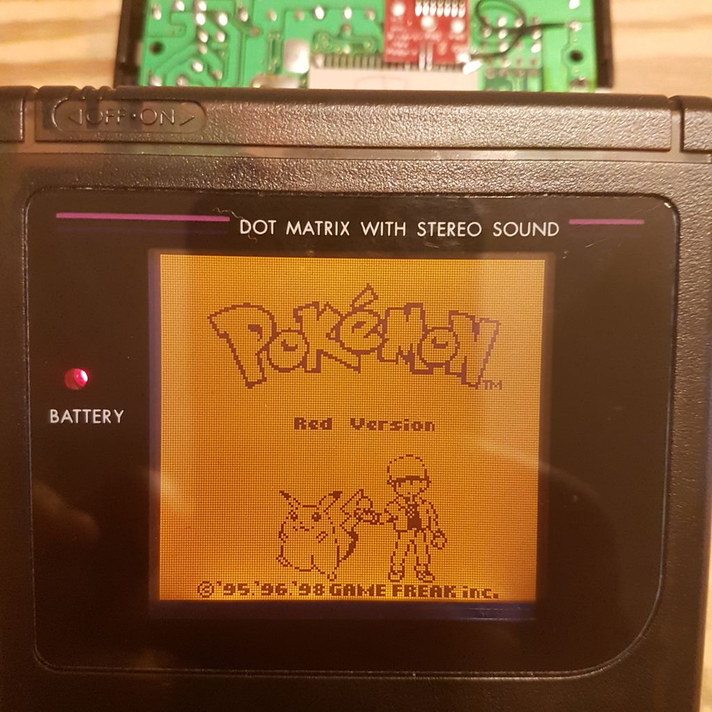
I did a backlight and bivert mod on A DMG-01, using a Deadpan Robot backlight kit and a Hand Held Legend pcb. After modding, all grey tones have disappeared, as shown in the following image:

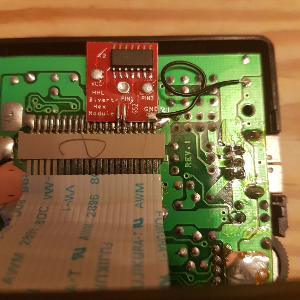
The connections on the bivert pcb seem correct according to HHL's instructions, can read any short circuits across the pins and the ribbon cable seems properly seated. Image of the pcb here:


Before I pull the bivert pcb to test if the system is otherwise working properly, I've gotta ask - has anyone else run into this problem, and, if so, any ideas on the cause?

Last edited by irony7 (Apr 19, 2017 7:08 pm)

Offline

Does the installation really not call for pins to be put through the pads? That's super janky. It's probably just not making full contact. Try adding a metal lead through the pads. Clip one off of a resistor or LED or something.

Offline

I will do it,  Apeshit!  Tried to reflow the solder through the the holes to ensure contact with the pads underneath, but that is a definite possible culprit.

Offline
irony7 wrote:

I will do it,  Apeshit!  Tried to reflow the solder through the the holes to ensure contact with the pads underneath, but that is a definite possible culprit.

Just keep them well trimmed, since that kit is mounted right under the ribbon cable carrying the high voltage for the LCD.

These kits really should be designed to be mounted on the back of the PCB...

Offline
Apeshit wrote:

Just keep them well trimmed, since that kit is mounted right under the ribbon cable carrying the high voltage for the LCD.

Will do.

Apeshit wrote:

These kits really should be designed to be mounted on the back of the PCB...

I've had success biverting with chips before, it's just that the pcb seem are so much sexier and take up less space.

Offline

I never said they shouldn't use a PCB. It's just mounted in a bad spot. Of course it will work, but it's bad practice to mount components under such a vulnerable spot. You could effectively use up half the space and still mount it on the back of the PCB.

Offline

Understood, Apeshit. And it makes a lot of sense.  I'll do your suggestion with a lead first, but will at the same time check out moving the board to tge other side of the LCD pcb.

Offline
NUMBSKULL

Here's a thing I had an issue with a while back: http://chipmusic.org/forums/topic/18845 … wo-shades/

Note where I cut the traces. Make sure you're not having the same issue.

Offline
catskull wrote:

Here's a thing I had an issue with a while back: http://chipmusic.org/forums/topic/18845 … wo-shades/

Note where I cut the traces. Make sure you're not having the same issue.


Tha nk you for that link, Catskull, looks to be exactly the same problem.  As soon as I get home from work I'll gewt my head around it and do the fix.  smile

Offline
Barcelona

did you fix this? i think i have same issue. How did it go?

Offline

Haven't done the fix yet.

Offline
Barcelona

ok, hope you done this fix, i have an issue with the hex vibist chip also, take a look:
https://chipmusic.org/forums/post/258348/#p258348