Offline
Australia

Goal:
I want to be able to swap (via a switch) between the regular crystal oscillator and the half speed oscillator, while also being able to swap (via a switch) between using a potentiometer to alter the clock speed and not using one.

Problems:
-I only have ON-OFF switches, and have no hope of getting ON-ON switches due to the fact that I have literally no money now, so the only hope is to see if I can work around it to achieve something similar.
-I do not have or want to use ON-OFF-ON switches here.

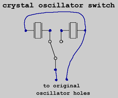
Here is a rather crude diagram of what I think I might be able to do to get around my problems (Crude in the fact that I didn't try to make the respective mods necessarily connect to the right places - the diagram is simply to show the ON-OFF switch workarounds):

Would this work? I don't know much about the behavior of electricity but I think it will... If I'm not mistaken, this should turn the switches into ONON-ONOFF, meaning the current will go through either one or both only. Here are some of the bigger questions in relation to this: With the current running through both crystal oscillators like in the diagram, what would the clock speed be? Would the effects of one override the other? Would the effects of both of them average out, resulting in a higher-than-half, lower-than-normal clock speed? Would the effects of both of them add or multiply, resulting in a fast clock speed? I'm hoping one cancels the other out; this way I can just put the one that cancels the other out where the half speed oscillator is on the diagram, and the other one first, achieving a seemingly ON-ON switch. Same questions for the potentiometer situation. I want to know everything I can before going in there and screwing something up badly.

Bonus / Unrelated questions:
-With Nonfinite's V3 backlight, is it the non ground wire that goes through an ON-OFF switch?
-Is there a good way to cut squares into plastic suitable for rocker switches? Right now the best method I've got is to melt a dodgy square with the soldering iron...

All help much much appreciated.

Last edited by Maple (Aug 10, 2011 11:13 pm)

Offline
Argentina

What I can say is that you have a short-circuit on the half speed crystal, and dont know if also has one on the pitch bend (dont know the pinout)

I tried to do something similar and my test gameboy is dead because of that xD
I tried to have a 3 positions switch: 0.5x 1x 2x
for that I used a 3 positions switch, one that have 8 legs, but if you only have ON/OFF switch, that I suppose that have 3 legs you can do...

                             SWITCH1
                                Leg 1----------------------->Pin1 Crystal 1 Pin 2<----+
Board Pin1-------------->Leg 2          Leg 1------>Pin1 Crystal 2 Pin 2<---+
                                Leg 3-------->Leg 2                                           |
                                                  Leg 3------>Pin1 Crystal 3 Pin 2<---+
                                                SWITCH2                                       |
Board Pin2------------------------------------------------------------------------------------+

I dont know the pinout for Pitch Bent, but I think you can change Crystal 3 for that
Hope that my ASCII art helps you

Last edited by Zuberi (Aug 4, 2011 3:53 pm)

Offline
Australia

Oh... Thanks but the switches have only two pins, otherwise I'd do something similar to what you suggested hmm (Your diagram shows what I'm trying to achieve; ON-ON switch functionality. But I only have ON-OFF switches) Also, how/where is the short-circuit?

The idea with my diagram is that the regular crystal is always on, but the 2nd crystal is only on if the switch is in the ON position. As for where the Pitch Bend pins are meant to connect... Well, I'm not sure, and I'd follow a proper tutorial to know where they go, but the general purpose for the diagram was to show the idea of bypassing the second crystal and the pitch mod always, but then being able to make the current go through those paths as well, with use of a switch on each path. So then my switch would (I think), in one position be cutting the line to the 2nd oscillator, and in the other position be joining it up, meaning both of the crystals are connected ... I wonder if this is a problem. I really don't want to try something without knowing and screw it up >_<

Oh also, that 3rd thing in the diagram is this.

Last edited by Maple (Aug 4, 2011 4:17 pm)

Offline
Argentina

if the first switch is off, half speed crystal is not connected, so only regular is set
if the first switch is on ,half speed crystal is short circuit, you have the same connection between the two legs of the crystal.
so will be the same if the first switch is on or off

Here is something that I don't know, if you can put crystals in parallel, in that case your switch could work, but will wait for some one else answer.

For the second switch, as I can see on the manual, one leg of the pitch bend goes to GND, the other to +Vcc (+3~6v), and the other to the on/off switch and then to one leg of the original crystal on the board, in that case you don't need to take out the original crystal. But have the same question as before here... if I can put in parallel crystals?

Offline
Matthew Joseph Payne

http://www.getlofi.com/?p=1794

The get lofi gameboy pitch mod basically runs the crystals in parallel.

Just do the two mods separately, with a switch for each. You can see how they interact later.

Offline
Australia

Ok. 2 quick things before I do it. 1: What do you mean by "basically runs the crystals in parallel"? Isn't there just the one crystal? and 2: What would happen if I actually used the 2 in parallel? I'm thinking of doing this...

Offline
Matthew Joseph Payne

Sorry, that was a terrible explanation. I'm pretty sure the getlofi kit starves (or force feeds) your crystal of voltage to change its speed, so there's no crystals running in parallel business per se.

The important (read: correct) part of what I was saying, is that you can do the half-clock mod and the variable speed mod completely independently and be sure they will both work, with the fun bonus of discovering what happens when you turn them both on, which is an unknown to my knowledge.

I'm assuming it might go a little slower, but will crash about halfway down.

Offline
Rhode Island

Getlofi pitch mod is independent of either clock. Though if you use it with the underclock I think kinetics assumption that it will crash at halfway is right, maybe even before that. Anyways, with two on/off switches you would run the crystals in parallel, but you would always have to turn one off and turn the other on. Not too sure what would happen if you just put the half clock in parallel with the regular and leave the regular on the board. Electricity would find the path of least resistance though which would likely be the original clock and your underclock wouldn't do anything. Go scrap up the change in your sofa and get an on/on switch.

Offline

You can't have 2 crystals connected at the same time. The GB will totally spass out. Get some money and use the ASCII schematic Zuberi made.

Offline
Matthew Joseph Payne

Installing the two mods separately is a lot simpler - you install the half-clock mod normally, so you have a witch that selects between crystals, then you install the get lofi mod, which will control the speed of whichever crystal is selected. ta da

Offline
Australia

Thanks for all of the help! I'm getting there.

Here is a random picture. The reflection was completely accidental which makes it all the more awesome:

Now, for my post:

I don't know how to install the half-clock mod seperately (but that might be a good Idea - read on)... Also, I ran into a problem. First I'll draw the circuit (the one I have currently soldered all up and stuff), then I'll explain what it's doing:


(That little chip is from Get Lofi - The 5 is +5, the O is output, and the G is ground. Extra note: I actually soldered the Half Speed crystal oscillator to the O on the Get Lofi circuit directly, but in the image above I drew an extra wire and made it separate because that was easier to draw, and it's still, as far as I'm aware, correct.)

Ok. So. The Half Speed switch doesn't seem to affect anything... Er, well, there seems to be a very slight difference in the mid-clock speed range but I'm not sure if I'm just hearing things because I want there to be a difference or not. When the potentiometer switch is on, everything seems to function correctly. I can bend the pitch and everything right. But, when the potentiometer switch is off... Regardless of how the Half Speed switch is, the clock speed just like, stops. I don't want to say 'crash' because, when I turn the potentiometer switch back on it continues correctly. At the moment I just want to be able to turn the potentiometer off, enabling the stock crystal oscillator, but I don't know which wire I'm meant to be putting the switch on since I thought where I was putting it was ok. Should it be on the output one? Or the ground? Or what? Then, if the Half Speed switch doesn't seem to be doing anything I want to install it separately (but I don't know how).

Thanks again for your help and support!

Offline
matt's mind

are those one-of-a-kind buttons?  (they look sort of like the purple/pink blend ones)...

Offline
Australia

They are indeed! I was originally aiming for a black/purple blend, or purple/dark purple blend, but this one is a tad darker than I thought it would be anyway so all is well smile

Offline
Matthew Joseph Payne

There's a couple problems with what you've got going on at the moment.  For one, the half-speed crystal is entirely dependent on the getlofi board - you would never be able to half clock without engaging the variable clock circuit.

Second, you have the two chips in parallel. I regret ever using that word in this thread. smile
However you install the half-clock, the switch needs to be able to select between the two crystals. This will involve desoldering at least half of the existig crystal.

from here: http://gieskes.nl/underclocking_or_over … _tutorial/ which will probably be helpful.

As for the speed pot not working, I recently transferred a getlofi modded game boy into a new case, and it had that symptom, but it turned out to be that the ground wire had become disconnected. I would check your solder joints.

Offline
Australia

Oh, thanks. It looks like I'm going to rewire the Half Clock crystal oscillator first then, because as far as I can tell, my ground wire for the potentiometer is wired solid and correctly. Then I'll see what problems I'm having and act accordingly or ask here.

As a side sort of off topic thing, when I did the prosound mod I think I accidentally severed one of the leads at the location you solder the wires to. The left headphone doesn't work at all on the new jack, and on the old jack the left headphone's output is significantly decreased. It seems really hard to get in there to fix the potentially severed wiring so I was thinking it might be easier to just solder an extra wire from where you solder the left headphone wire to, to an easier place on the board. It's hard to see where the lead gos though, because the copper plate covers it. Any ideas?

Last edited by Maple (Aug 8, 2011 5:06 am)

Offline
Matthew Joseph Payne

Your description of the prosound problem could be a short caused by a solder bridge. I'm not sure what you could have severed, as you have to put in some significant effort to cut traces on the PCBs. It would be hard to say for sure without seeing it in person, but some clear photos of what you've got going on so far might be helpful.

The best advice I can offer you right now is to do these mods one at a time, making sure you have one working solidly before you dig into the next. smile