Thank You Nitro2k01 you have helped you on a part of my track that i got writers block on.
This patch should be very useful. Thanks
chipmusic.org is an online community in respect and relation to chip music, art and its parallels.
You are not logged in. Please login or register.
ChipMusic.org / Forums / Posts by SAMWAVE
Thank You Nitro2k01 you have helped you on a part of my track that i got writers block on.
This patch should be very useful. Thanks
neailbaldwin I am very happy to hear of this project.
As a further bonus I'm even happier that your such a enthusiastic individual to be working on such a great project. ![]()
Exceleltn piece starscream I am still enjoying your previous album 'Future, and it doesn't work'; your stuff is remarkable.
The thing you are calling a cathode is actually called a resistor, you might want to edit that.
Also you left the legs on the resistor should have been cut a bit shorter and cover with shrink tube or tape.
Other than the, very nice tutorial, very clear on every step
hehe thought i made a mistake with the 'cathode,much appreciated TmTgr will change it now.
Thanks for this, SAMWAVE. Glad to see so many people lighting up their DMGs and pockets with these things. ^^
Nonfinite never knew you was on this site. No probs anyways about this tut was fun to make and I hope it helps some people out.
Cheers for the feedback so far guys ![]()
Nice tutorial. some of the pictures could be a bit clearer, but this should help peeps a lot w/ their installations!
DIY 4 LIFE!
Thank you Low-Gain much appreciated with your feedback ![]()
When I get hold of a more decent camera I will gladly take some clearer shots.
Hey nice website ![]()
This is gunna be my new home I hope =]
Hey yesterday my backlight kits that i ordered from http://nonelectronics.com arrived. I had the idea then to design my own tutorial based on nonfinites for the completly new beginner. I apologise for the bad photoshots as it was only me doing this throughout the whole process.
If the pictures seem unclear to you click on the image and a larger version will be shown.
This tutorial is a bit long winded but hopefully it will do its mission by aiding you to backlight your gameboy.
[size=200]WARINING I AM NOT RESPONSIBLE FOR ANY DAMAGE TO YOUR EQUIPMENT/GAMEBOY THROUGHOUT THIS TUTORIAL DO IT AT YOUR OWN RISK![/size]
Before I began to Mod my gameboy I thought I would make a tutorial for the Chip Coalition newbies/members but I also think it may be good for Chipmusi.org as well.
[size=200]HERE IS THE EQUIPMENT YOU WILL NEED:[/size]
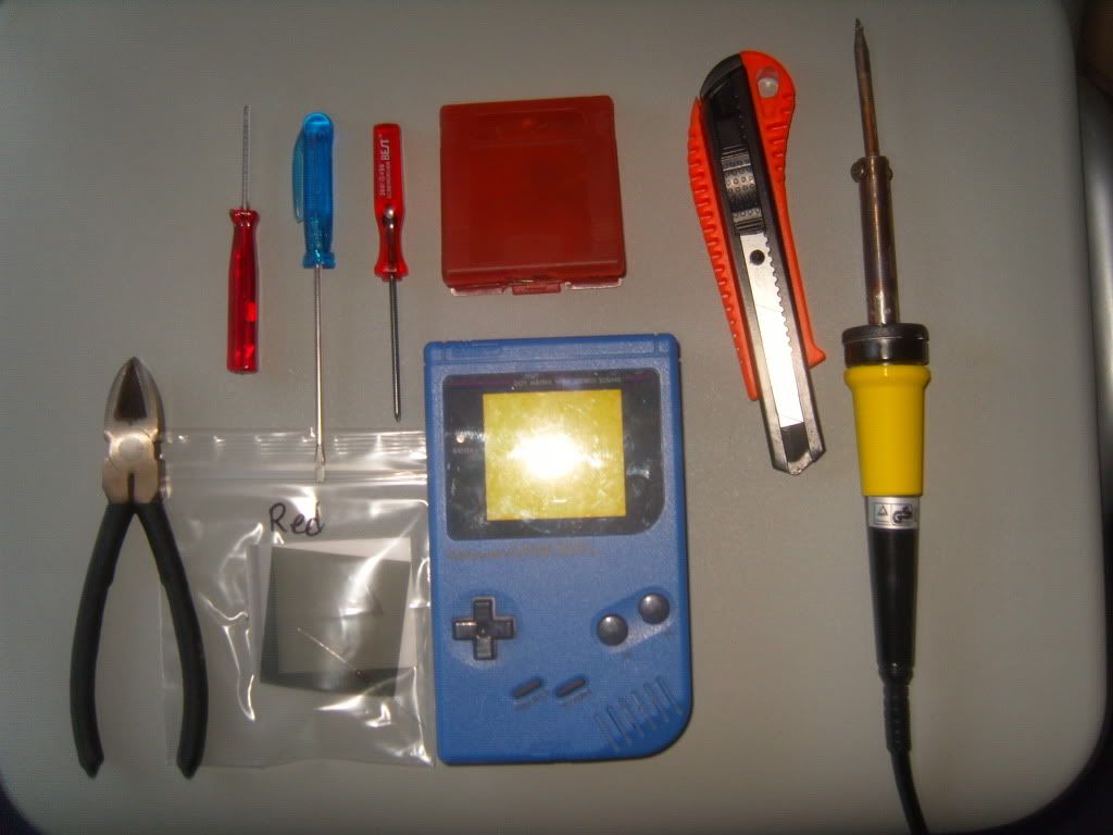
As you can see there are:
-Tri wing screw driver (can buy from various places on the net)
-Flat end screw driver
-Phillips headed screw driver (a small one will be needed)
-30watt Soldering iron
-Stanley Knife
-Backlighting kit (that you can buy exclusively from nonfinites site)
-A pair of clippers
-Somewhere to store your screws (I used an old gameboy cartridge protective case)
- A Gameboy Handheld Console
(Safety equipment is recommended for your safety such as protective glocves, eye protection and a fume mask)
1.
Turn Your gameboy so its battery compartment is facing you and unscrew the screws with the Tri Wing screwdriver make sure you unscrew all 6 screws.
2.
Open your gameboy as it should be in two pieces, be careful not to pull it open too far though otherwise you may damage the white ribbon cable which is attaching both sides of the gameboy together.
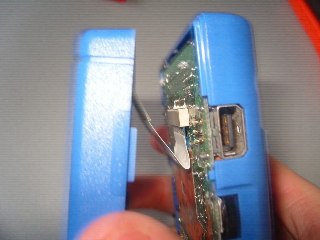
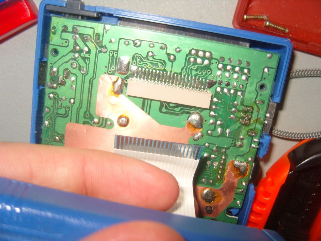
3.
Be careful and move your gameboy so you can carefully hold the ribbon cable between your thumb and index finger. Then apply pressure downwards be cautious yet don't be too scared of pulling the cable (its stronger than you think) ![]() .
.
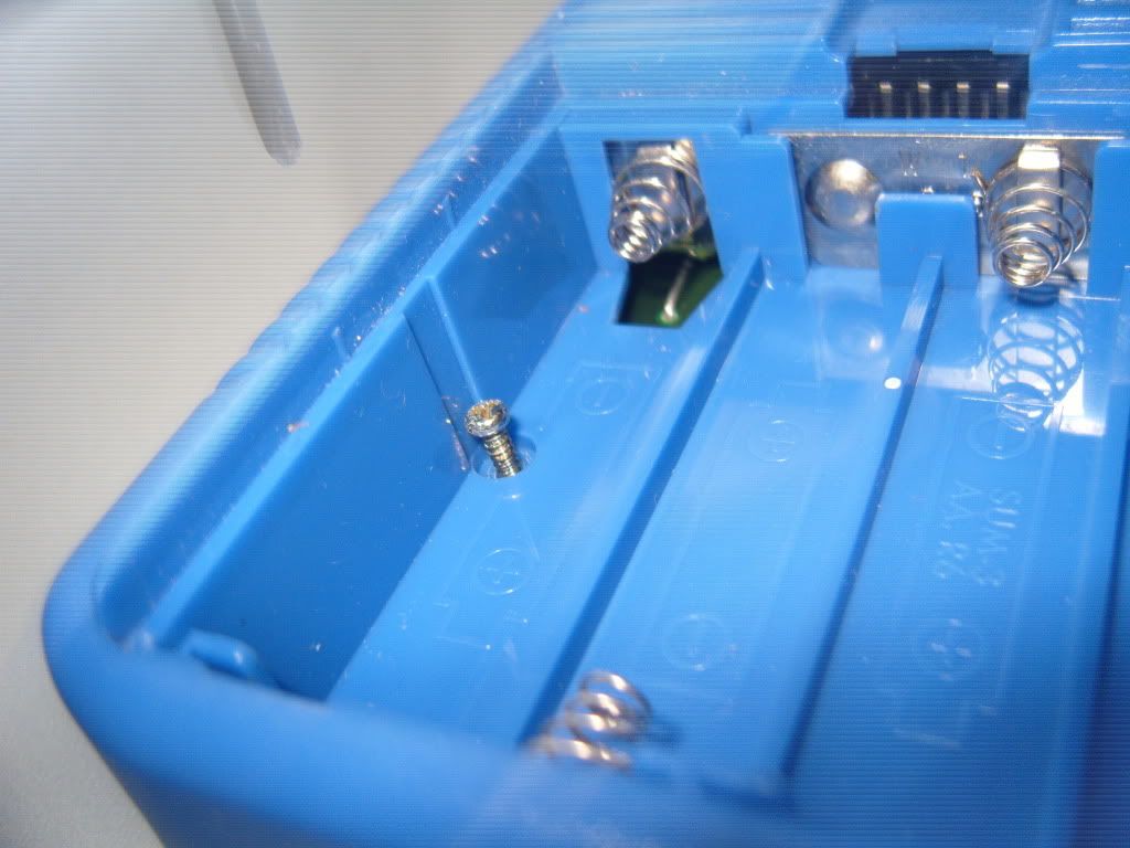
4.
Right now you have a gameboy in two pieces use the side of with the ribbon cable attached to it and unscrew the screws with the phillips screw driver. Down below i have marked out in red the areas of where the need to be unscrewed.
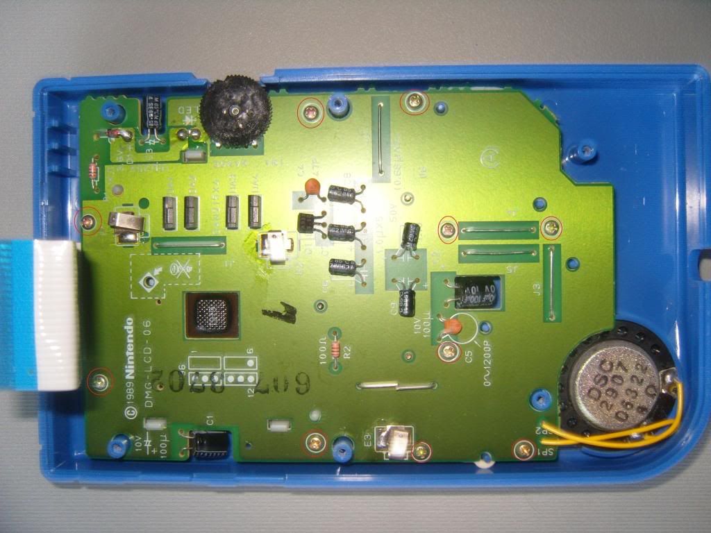
5.
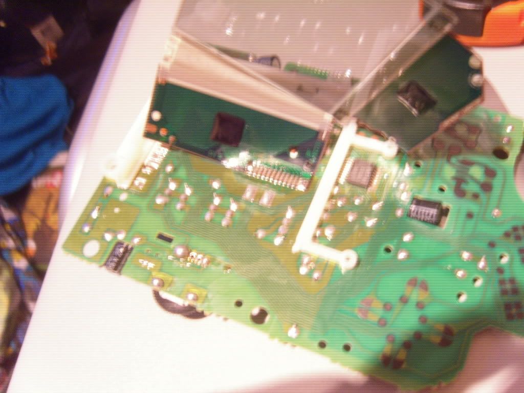
Once all is unscrewed you should be able to pull the pcb out of its protective gameboy case.
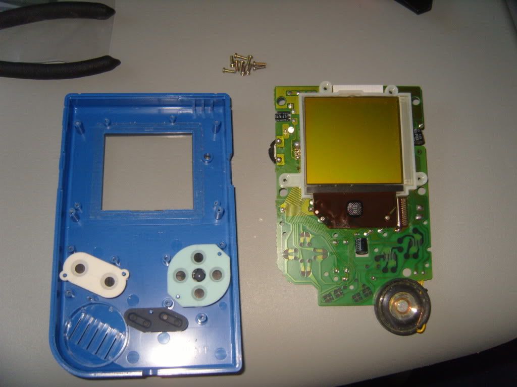
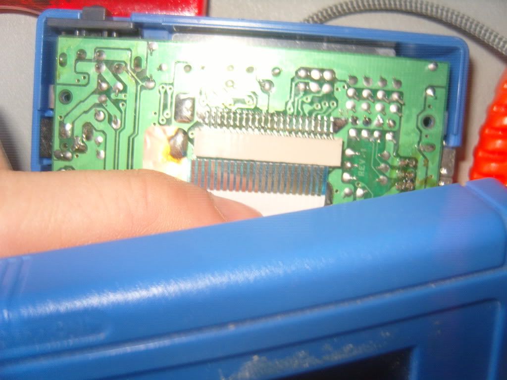
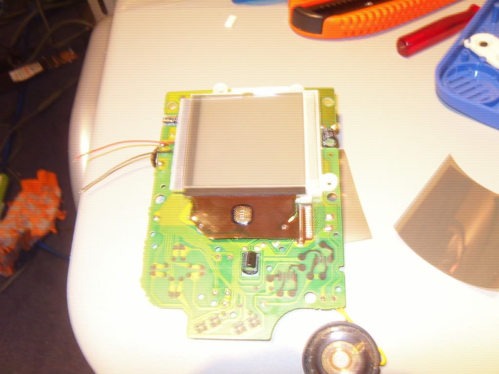
6.
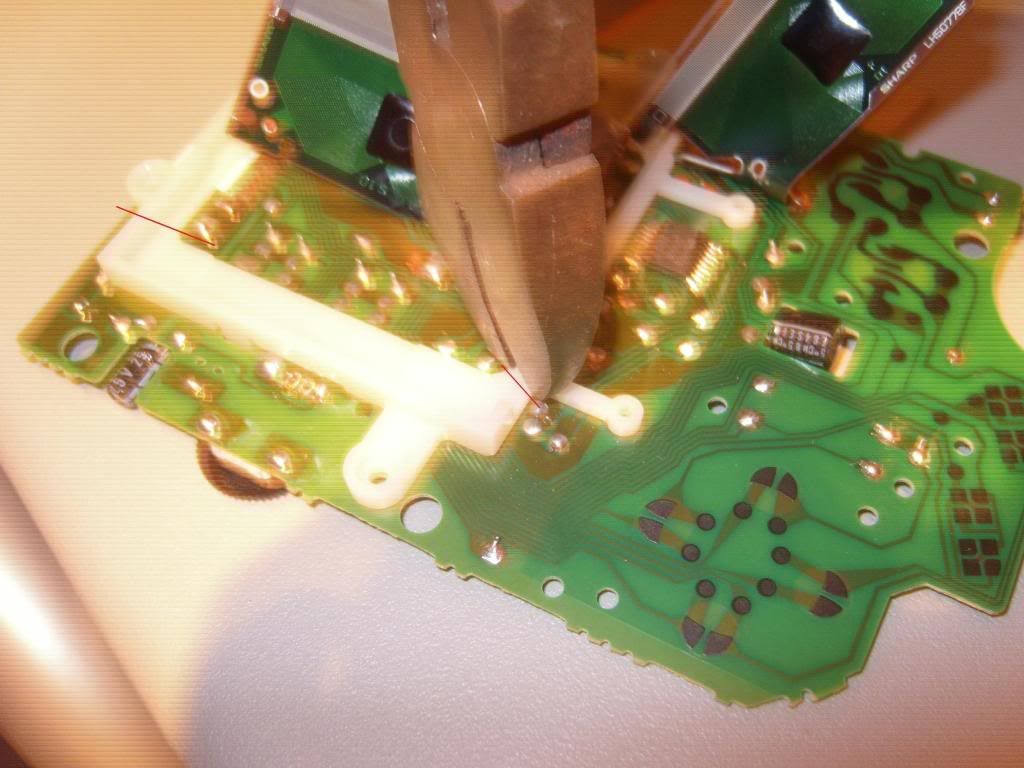
On the PCB you will see two screws on it , you will need to unscrew these with the philips screw driver but be very careful not to damage this cable other wise you may kill some pixels on your screen. Here is a picture with the screws marked out once again:
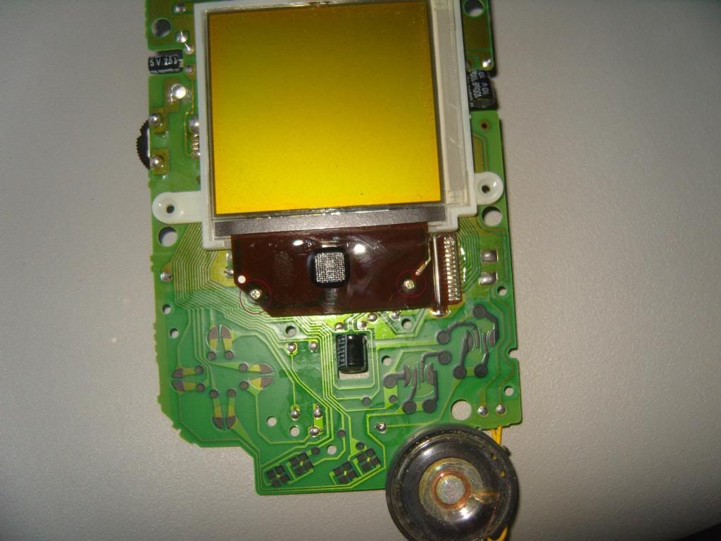
7.
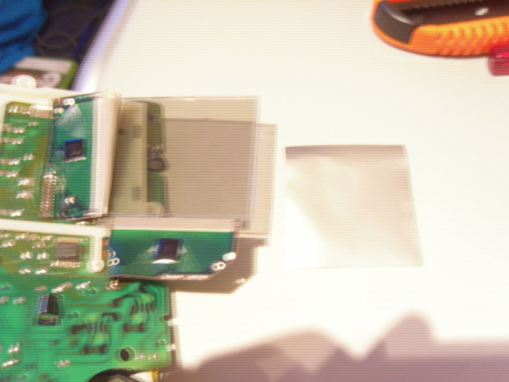
Ok now you will need to use the Flat headed screw driver to put into the gap on top of the screen (should be able to see a little gap), once the screwdriver is in put some leverage force into it so that the screen will pop out.
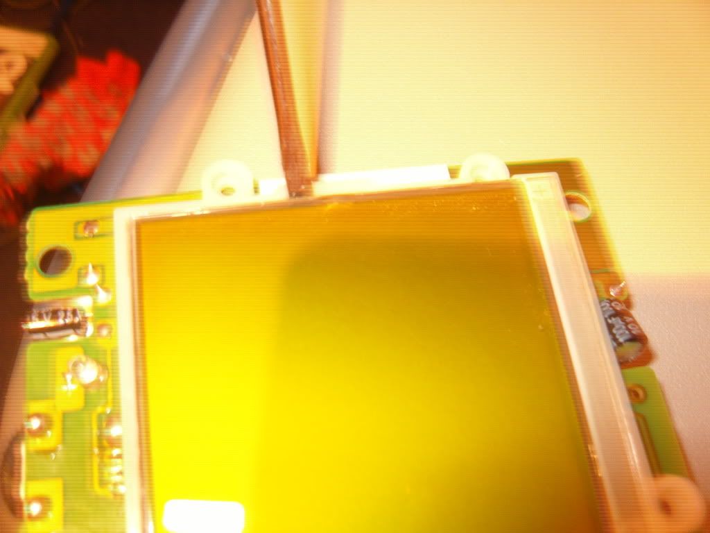
8.
You will see some white foam pads underneath the screen, just remove them and dispose of them. Now its time to grab you stanley knife ready for the next stage.
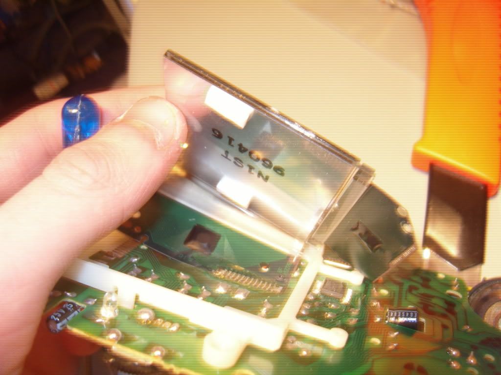
[size=200]THIS IS THE MOST DIFFICULT PART OF THE MOD, BE VERY CAREFUL AND TAKE YOUR TIME! [/size]
9. Get your stanley knife and slide it just under the silver coloured foil but make sure you dont end up scraping the glass. Once the knife is under slide it so a bit of the foil is easily grabable by your thumb and index finger.
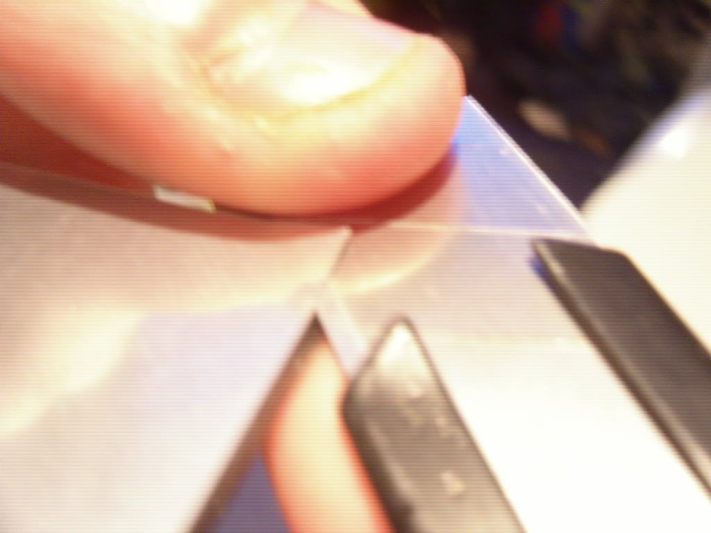
10.
Now carefully and I mean carefully ! ! ! Slowly begin to pull off the foil, this part maybe time consuming but just use the force of your strength to pull it off as it is the easiest and best way of removing it without screwing up the screen. Once done you screen should look good and clear.
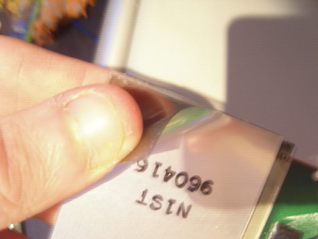
Done:
11.
Now grab your soldering iron and remove the LED (the power up LED) on your gameboy PCB.
12.
Lift your screen up and use your snips to cut the plastic border at the red line points that i have done for you in this image:
Here is the done result should look like:
13.
Now slide in your backlighting kit (I am using version 2.0 backlight kit), make sure the red and black wires are clearly out of the inside of your screen.
14.
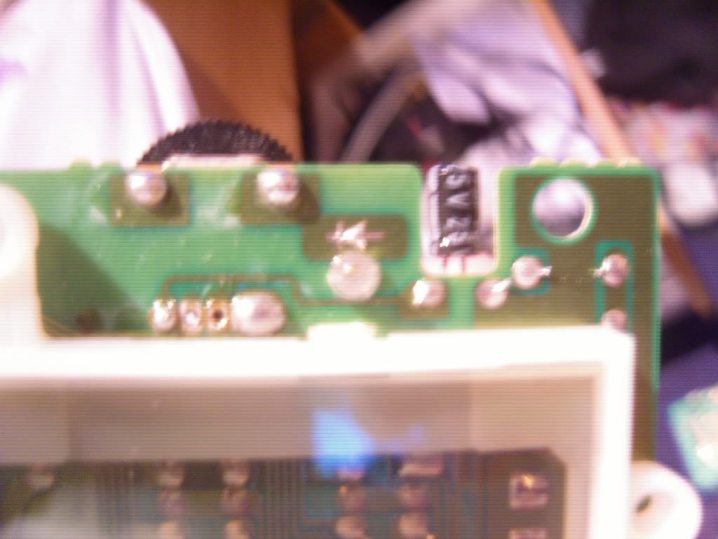
Now at the top left corner of your PCB there will be 3 points of where your gunna have to use you soldering iron to remove these resistors.
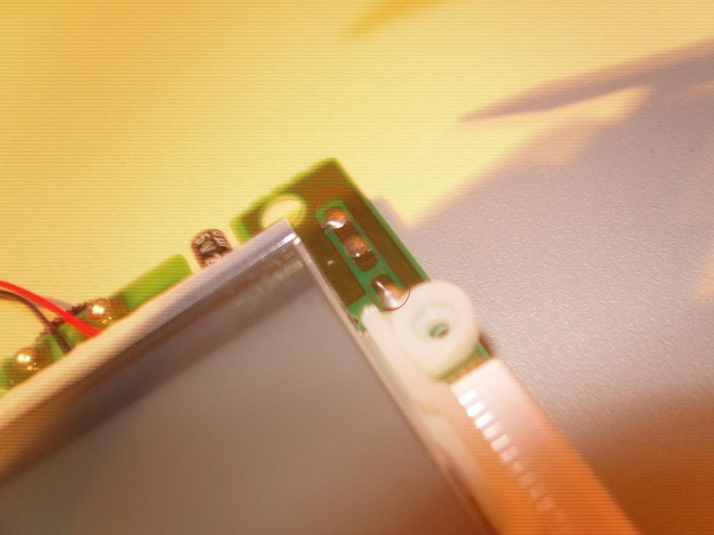
15.
Once the resistors have been removed put in your resistor that came with your backlight kit through the nearest hole to the screen (if your looking at your Dmg PCB frontwards it would be the far right hole that you have just made from removing the resistors). Once the resistor has been soldered appropiatly you can snip off the legs off it that are poking out.
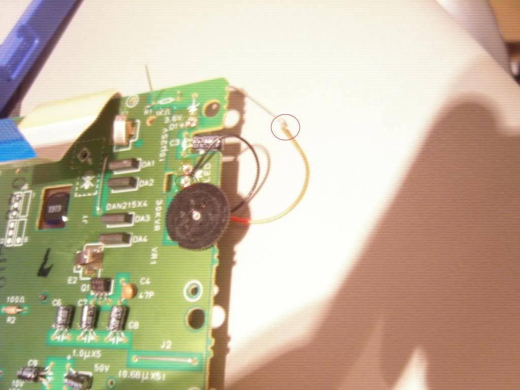
16.
Once done solder your RED wire of the backlight Kit to the resistor and solder you BLACK wire to the LED hole (the hole that is closes to the contrast dial).
17.
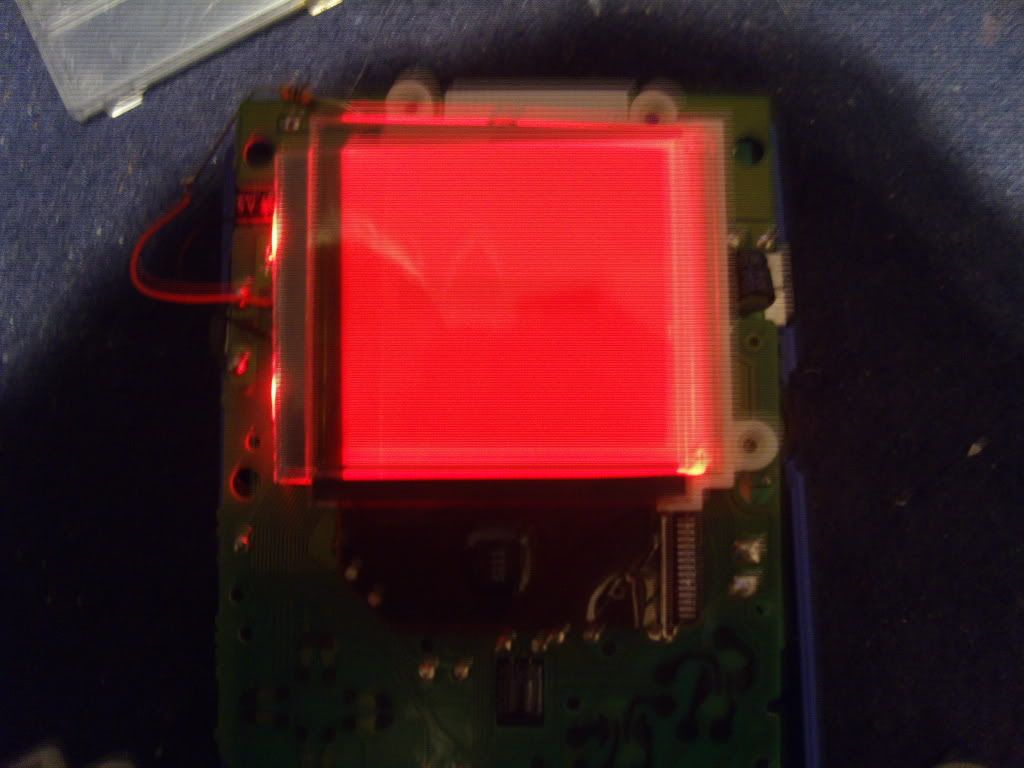
Once done slide in your polarising film between your screen and backlight kit, attach the ribbon cable to the other part of your gameboy and flick the power switch on and here should be your result:
[size=200]Polarising Film What you can do with it:[/size]
As you can see withinin your kit you have a single piece of polarising film. I will not go into detail of how it works although there are two options you can choose in order to make your LCD screen display either one of the two types. In order to make your gameboy inverted or non-inverted all you have to do is 90 degree turn the polarising film when you have placed it inbetween the kit and screen. Here are the benefits of non-inverted and inverted:
A Non-Inverted screen benefits are:
-Make the gameboy display visible without light (if you have modded it with a switch to turn backlight on and off p.s. the switch technique is not included in this tutorial).
-Appearntly blue looks great inverted although I have a pink inverted and I say it looks great.
-When the gameboy is turned off the screen looks green.
Inverted Screens benefits:
-They look great
-All the colours become the opposite such as black becomes lighter and lighter colours become dark (trust me try it yourself an see how nice it looks).
-I also have no problem watching whats on the screen even if external light is in the way.
-When the gameboy is turned off the screen will be coloured blue.
Overview:
Choose whichever suites you best, some people find inverted better well as other people say non-inverted is better; at the end of the day its your choice. I would have provided pictures but i cannot get any clear ones as the screens are too bright. Down below I have designed a rough picture of what it looks like though on MS paint:

This is what a non-inverted (normal) screen would look like.

The image above is what an inverted screen would look like.
As you can see the pictures are the opposite colours of eachother (this is what basically inverted and non-inverted screens look like when displaying text).
These pictures are just to give you a rough idea of what inverted and non-inverted screens would look like. Just try it out yourself it only takes a few seconds to do and in real life the whole thing looks alot more better due to the colour of your kit ![]()
TA DA !! Your backlight kit is working ![]() Congratulations but there is one more thing to do.
Congratulations but there is one more thing to do.
18.
Now all you gotta do is screw your gameboy back together and your done! Here is an image of my final product:
Switched off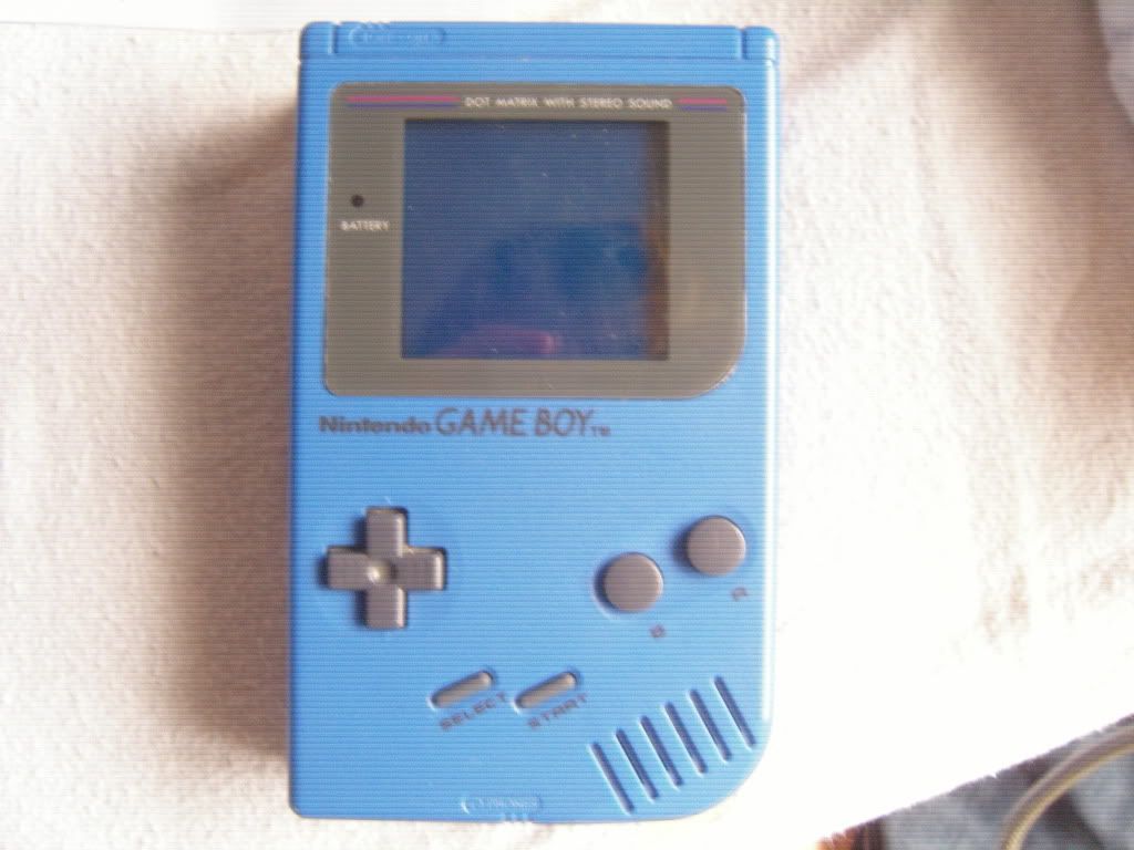
Switched On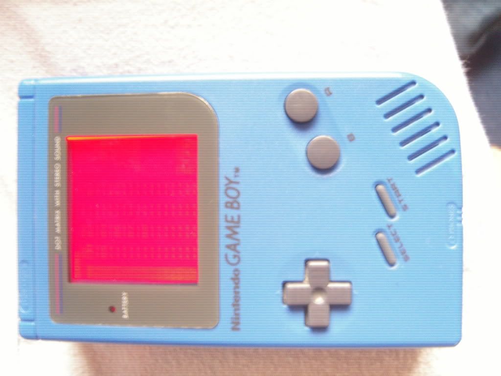
If this tutorial helped you please leave a responce on this thread. I would like to thank Nonfinite for his tutorial http://nonelectronics.com/tutorialsmt.php which helped me grately. The aim of this tutorial is for someone who has no experience what so ever from opening a gameboy to modding one. Hope you have enjoyed reading this tutorial many thanks.
SAMWAVE [myspace.com/SAMWAVE]
ChipMusic.org / Forums / Posts by SAMWAVE