Yep. I would have to agree. I still cannot get Chipmaestro to work. It will play back keyboard notes when using the USB/MIDI cable but won't play back midi tracks I've written out.
97 Mar 16, 2014 6:04 pm
Re: Cheap USB to MIDI Cable for Arduinoboy? (44 replies, posted in Nintendo Handhelds)
98 Mar 14, 2014 8:17 pm
Re: USB-BOY BY THURSDAY CUSTOMS (1 replies, posted in Product reviews)
Niceeeee ![]()
99 Mar 14, 2014 3:22 pm
Re: Cheap USB to MIDI Cable for Arduinoboy? (44 replies, posted in Nintendo Handhelds)
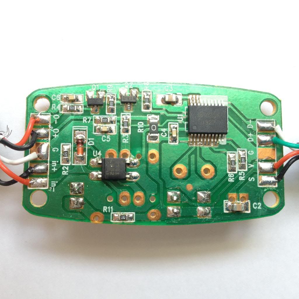
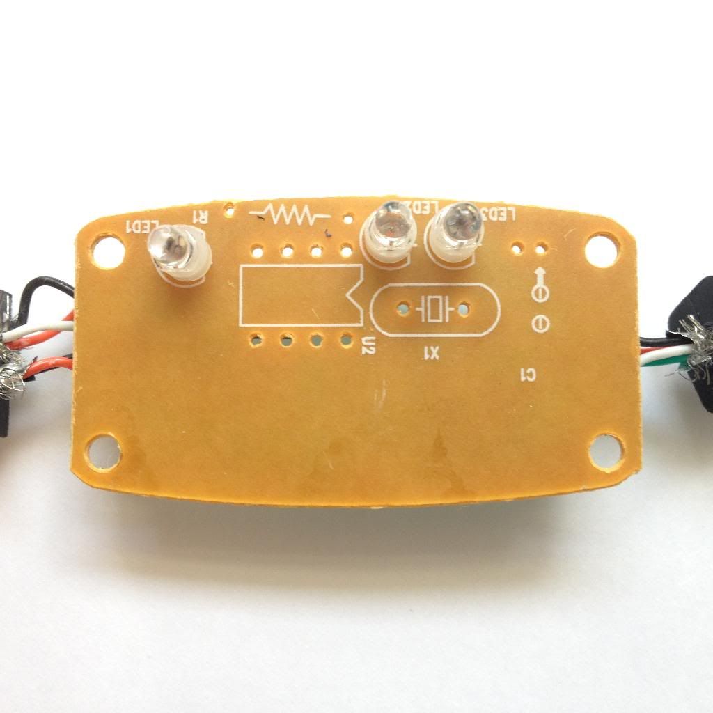
Thanks! Just got mine in yesterday. I believe the holes are for alternate components like a DIP8 IC instead of the 4 pin SMD IC there towards the bottom left. Also there is a spot for a crystal oscillator and an through hole resistor instead of the SMD one that is already there.
Mine seems to work for the most part. It's very glitchy though. It doesn't want to trigger more than the first note most of the time and won't really let me control the envelope in mGB. Oh well.
100 Mar 11, 2014 1:13 am
Re: DMG Prosound Question (26 replies, posted in Nintendo Handhelds)
The stock headphone jack is actually what shuts the speaker off. There is no jack in existence(that I know of) that works the same way. The signal to the speaker actually runs directly through the headphone jack and is then cut off when anything is plugged in. A prosound jack will never do this unless you prosound the stock headphone jack.
101 Mar 10, 2014 4:53 pm
Re: DMG Main Board Schematic & Circuit (+Arduinoboy) (72 replies, posted in Nintendo Handhelds)
bit 9 wrote:Ok, so let me pick your brain for a moment. How on earth do you make oblong through-holes? I'm doing unspeakable things with layers to get the battery contact points, DC jack, switch, and link port to look right. Part of my reluctance of releasing the file is that whole 'there has to be a better way to do this' thought.
check this out, we discussed this very thing farther down in this thread
That's what actually spurred our discussion on oblong pads. He edited that post before we started talking about it.
102 Mar 10, 2014 4:31 pm
Re: DMG Main Board Schematic & Circuit (+Arduinoboy) (72 replies, posted in Nintendo Handhelds)
I’d imagine most everyone here would recognize this image. (In someone else’s words:) “It's surprising how much good that crayon drawing has done for the chiptune world…” I hope I’m not stepping on anyone’s toes when I say it could be a little more readable.
So that’s why I’ve added this.
It has Gameboy Genius’ fix to prevent lost MIDI notes when running off GB power. An addition I wouldn’t mind being better known, because it took me some time to come across it. So, while I’m dumping technical documents like so much unwanted bologna, I’m hoping someone who Googles to this page learns about it faster than I did.And while I’m at it
This
This is a fairly small, 1 sided Arduinoboy measuring in at 1.875 x 1.55 in. The thought I had in addition to making it a companion to the schematic above is that this is an easily etch-able circuit board. If you don’t know what I’m talking about check this out, but there are several other ways to do this.
That’s why there’s this black and white version for you to print out. If you are going to etch this, make sure you flip it if your method requires it. This image is at 1000dpi, because I can, and a decent laser printer can do it. Eagle outputs aliased images, so high-res-ing the image is a way to get around any jaggy problems. I took the liberty to make the holes smaller so that when you drill you’ll have copper right at the edge. If you do use this, post it here and let me know how it went!Also, also: if you've googled to this and don't know what this is - this is the answer you're looking for.
This is really great. You should see if Trash80 would be willing to replace the current schematic with this one as well as add these board images.
103 Mar 10, 2014 4:21 pm
Re: GBC Prosound Help (11 replies, posted in Nintendo Handhelds)
Either you have a soldering issue or the volume pot is dirty. Try using a q-tip to put a few drops up rubbing alcohol hinder the volume wheel. Turn it up and down for a minute or two. Let dry for about 15 minutes and see if it sounds cleaner.
104 Mar 9, 2014 6:18 pm
Re: Super Game Boy and LSDJ? (14 replies, posted in Nintendo Handhelds)
The SGB is a great workshop type tool. I had a few of the Piko Piko guys stay here one night and Monotony was all showing us LSDJ tricks on the SGB while we all had our own Game Boys in our hands. It was really fun!
It's also probably a pretty good studio setup as you could connect a monitor and not really have to worry about anything but the controller.
And not intending to try to promote here but we just released a kit that allows you to easily add a link port to an SGB so you could use a keyboard, USB-Boy or Arduino Boy.
105 Mar 9, 2014 6:15 pm
Re: Twitch Plays Chiptune (4 replies, posted in General Discussion)
Some people just want to see the world burn...
106 Mar 8, 2014 8:48 pm
Re: DMG Main Board Schematic & Circuit (+Arduinoboy) (72 replies, posted in Nintendo Handhelds)
Will do!
That's lame ![]() I was trying to place a large batch order too!
I was trying to place a large batch order too!
107 Mar 8, 2014 8:27 pm
Re: DMG Main Board Schematic & Circuit (+Arduinoboy) (72 replies, posted in Nintendo Handhelds)
from the last part of that manual snippet:
"Please inform your board manufacturer that they have to take care on the
milling data drawn in this layer. Also tell them whether they should be
plated-through or not."
you'll want it plated-through
Right. Oshpark simply doesn't answer emails though ![]() so I just have to see what happens. They automatically have platted slots in the past so maybe this will work out! Just ordered a few PCBs to see what happens.
so I just have to see what happens. They automatically have platted slots in the past so maybe this will work out! Just ordered a few PCBs to see what happens.
108 Mar 8, 2014 7:22 pm
Re: DMG Main Board Schematic & Circuit (+Arduinoboy) (72 replies, posted in Nintendo Handhelds)
Okay. So instead of making new parts I will sometimes just go and edit parts that I know I would never use otherwise.
If you right click an object on the board page you can select "Open Package". This allows you to edit it however you like.
So I set the pad shape to "long" and added a "milling" layer(you can barely see it since it's a light bluish color but I promise it's there!).
*side note: the text on the pad is just my own notes. i write them in the "tDoc" layer so it doesn't mess with the actual upload. this has been very helpful since i often edit parts like this*
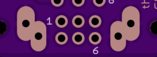
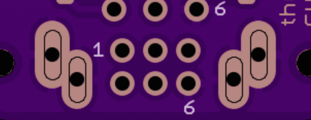
Eagle was able to connect the pad using ground planing exactly how I wanted it to but Oshparks preview did NOT recognize the "milling" layer: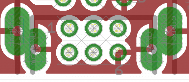
So I changed the "milling" lines to "dimension" lines. This of course would not allow the ground plane to reach the pads since I have the distance set at 20mils. I forgot that Oshparks preview doesn't actually show them being milled out but it does show the lines. This has always worked flawlessly for me as: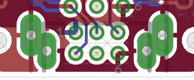
So maybe I will order a batch of PCBs with the "milling" lines and see if it ends up getting cut out! If not then at least all you have to do now is add tracing lines and not tStop, bStop, tRestrict and bRestrict. Either way this definitely makes it a whole lot easier!
One very small downside is that when you choose shapes in the "Design rules" you have to chose "as in Library" for the pads to be long. Otherwise they will be whatever option you chose. So basically you may have to go back and edit all the pads in the packages to be round or whatever shape you prefer.
Okay. I think I have to sign off. I've spent wayyy too much time on this today! I gotta get some work done!
109 Mar 8, 2014 6:32 pm
Re: DMG Main Board Schematic & Circuit (+Arduinoboy) (72 replies, posted in Nintendo Handhelds)
Ah yeah that's true. I've never had an actual problem with my boards like that though I have noticed pads that were supposed to have different drills ended up being exactly the same. Didn't hurt anything though. But as you said the preview will at least be correct for reference.
110 Mar 8, 2014 6:27 pm
Re: DMG Main Board Schematic & Circuit (+Arduinoboy) (72 replies, posted in Nintendo Handhelds)
And yes I think you will still need "restrict" and "stop" layers on top of either method. If you're making a part though they should be included in whatever pad you use. So "milling" should not affect the distance of the ground plain from the pad but "dimension" certainly will. Making a part is starting to sound a lot easier to me now!
111 Mar 8, 2014 6:24 pm
Re: DMG Main Board Schematic & Circuit (+Arduinoboy) (72 replies, posted in Nintendo Handhelds)
Try uploading your board to oshpark.com. It will generate an image of what your board should look like. It shows you all the main layers so you will see how either layer will affect the outcome.
112 Mar 8, 2014 5:53 pm
Re: DMG Main Board Schematic & Circuit (+Arduinoboy) (72 replies, posted in Nintendo Handhelds)
from the EAGLE Manual
"
8.11 Components with Oblong HolesIf the board manufacturer have to mill oblong holes, you have to draw the
milling contour of oblong holes in a separate layer. Usually this is layer 46, Milling.The milling contour for components that need oblong holes can be drawn
with WIRE (and possibly ARC) with a very fine wire width near or even 0 in the Package Editor. Take a pad that has a drill diameter which lies inside the milling contour, or SMDs, for example in Top and Bottom layer, as basis for the oblong hole.In case of a multilayer board you should draw a WIRE in the used inner
layers at the position of the oblong holes so that it covers the milling contour and leaves a kind of restring around the opening.Please inform your board manufacturer that they have to take care on the
milling data drawn in this layer. Also tell them whether they should be
plated-through or not.
"hope that helps! its not too bad.
you all may also want to create a custom library called "oblong holes" if you have a need of them individually (rather than as a part's footprint). its a time saver
Nice! Thanks, Matt! It only sounds slightly easier than my method. An oblong library is a good idea though! I wouldn't be surprised if there is already one out there.
