33

(11 replies, posted in Nintendo Handhelds)

Apeshit wrote:

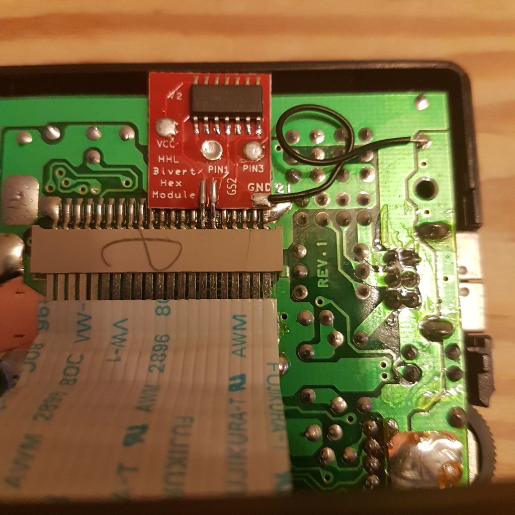
Just keep them well trimmed, since that kit is mounted right under the ribbon cable carrying the high voltage for the LCD.

Will do.

Apeshit wrote:

These kits really should be designed to be mounted on the back of the PCB...

I've had success biverting with chips before, it's just that the pcb seem are so much sexier and take up less space.

34

(11 replies, posted in Nintendo Handhelds)

I will do it,  Apeshit!  Tried to reflow the solder through the the holes to ensure contact with the pads underneath, but that is a definite possible culprit.

I did a backlight and bivert mod on A DMG-01, using a Deadpan Robot backlight kit and a Hand Held Legend pcb. After modding, all grey tones have disappeared, as shown in the following image:

The connections on the bivert pcb seem correct according to HHL's instructions, can read any short circuits across the pins and the ribbon cable seems properly seated. Image of the pcb here:


Before I pull the bivert pcb to test if the system is otherwise working properly, I've gotta ask - has anyone else run into this problem, and, if so, any ideas on the cause?

36

(11 replies, posted in Past Events)

Olio wrote:
irony7 wrote:

Do you have some graphics for promoting the event/kickstarter?  (A4/A5 flyer, A3 poster) I could print a bunch up at work and distribute them around town here.  smile


Sure! Here is the poster A3: https://we.tl/Md3mRXmsth

Thank you so much for this help!!!

The summer is not even started yet but i already want the end of it tongue

What about adding contact info/url to kickstarter, fb to the poster? I could do it, but don't want to screw up the great graphics. 

37

(11 replies, posted in Past Events)

Yeah, defensem3ch, you need to check out Christiania, the local retrogamer spots, the street food island...lemme know dates and we can meet up maybe, definitely figure out some stuff for you to see.

Apeshit wrote:

I should rephrase that... Connecting directly to the battery terminals won't turn off the backlight when you switch off the gameboy. So yeah, power LED source is a good place to tap into.

Haha,  good point!!

Apeshit suggests running the backlight unregulated directly from the battery terminals - I'd go with that.

edit - rereading it all, I would run it over the power led, no need then for running wires between the boards.

toasterpastries wrote:

I am honestly in the middle of the same thing... BennVenn RGB controller with KB RGBx3. I've got it working but I screwed up some of the solders getting it all buttoned up. I'll try to offer some advice later when I can take some pics.

Thank you, toasterpastries, looking forward to it!!  big_smile

What about running an extra regulator (buck/boost 5v dc-dc) parallel to the stock regulatorer to power the backlight?  Could that work to relieve the stock regulator from overheating?

I didn't realize there was unregulated power running through the beast, Apeshit, good to know.

The batteries cut out when running the Gameboy on external power through the 6v in jack, don't they?  Better over the LED then.

Apeshit wrote:

I'd desolder the backlight and add somewhere around a 47 ohm resistor and tap into the unregulated power source to bypass the regulator.

Unregulated power source = directly from the batteries, Apeshit?

The heat could degrade the electrolytic capacitors, so yes, possibly.

On this image of the back of the new model power regulator board you can see the revision model DC CONV2 DMG:

This board SHOULD not have overheating problems, by all accounts.  The older power regulator board, the DC CONVERTER DMG, has, I understand, a tendency to heat up.
You can check the board type without removing from the shell by checking how many black barrel caps the board has - the new one has three, the old one has only one.
Alternatively, you can check the CPU revision type of your DMG. Ifor you peek through the hole the push tab of your battery cover goes through, you can see the text "DMG-CPU-0x", where"x"is a digit from 1 to 8.

The CPU revision for the DMG in the picture is a 06, and has the old style board.  The 07 and 08 revision should have the new board (with less chance of heat buildup).

It's the little board that sits alongside the battery compartment.

It comes in two revisions, the newest being labelled DC CONV2 DMG on the side of the board facing the battery compartment.  The older version has a tendency to heat up, I understand from reading DMG-01 hardware descriptions.  I forget when the older version was phased out, generally it'seems recommended to use a CPU revision 07 or 08 to address this problem - with those revisions you will be getting the new version power supply.

Which CPU revision does your DMG have?

46

(11 replies, posted in Past Events)

Do you have some graphics for promoting the event/kickstarter?  (A4/A5 flyer, A3 poster) I could print a bunch up at work and distribute them around town here.  smile

Power regulator heating up, perhaps?

If the Prosound jack is located in the corner on the bottom of the upper shell to the left of the headphone jack, it's right next to the DC converter board. I understand there are heat issues, especially with early revisions of that board.

48

(11 replies, posted in Past Events)

Let me know if you need any help promoting in Copenhagen.  (Bip Bip Bar, Ruben and Bobby both located here)