Two IC's, some resistors and a cap. 4066 analog switch, 4093 schmitt NOR.
I don't know what your audio source looks like, ac/dc coupled, 1-10vpp, etc. You can also use this method to control any buttons you might have in the device you're "bending". There are several unused gates after all. If you do leave the gates unused, make sure to tie the inputs to either vcc or gnd and leave the outputs hanging.
Also worth mentioning that your vcc will effect the speed of the oscillation. 
49 Jan 8, 2020 2:53 am
Re: Stutter Switch?? help (2 replies, posted in Circuit Bending)
50 Jan 7, 2020 1:57 am
Re: BleepBloop / UCP woes (6 replies, posted in Nintendo Handhelds)
What program is that?
51 Jan 6, 2020 12:19 am
Re: Power LED Blocks Audio in Bent Book Strip (9 replies, posted in Circuit Bending)
AAA's will provide more current than the coin cells, so that should help with the dimming.
To be honest, we have to assume it is an unreliable power source. The audio circuit probably takes everything it's got just to work, so dimming of the LED is expected. Whats happening is that once all of the available current is being drawn, the voltage begins to droop. So if there is more current available, the voltage will remain more stable.
There are a few things we can do once you swap in some AAA's.
1. you can increase the resistor value.
2. you can wire a transistor in the mix to regulate the amount of current the LED gets.
But you may not need to do either of these once the power supply has more "juice" to offer.
52 Jan 5, 2020 9:55 pm
Re: Power LED Blocks Audio in Bent Book Strip (9 replies, posted in Circuit Bending)
southboundpachyderm wrote:
Thank you! That solved the problem. I'm still pretty ignorant about certain components, so that was a good lesson.
It's powered by three coin cell batteries, by the way. Would it be better to replace those with larger batteries?
I wouldn't just replace the batteries with larger ones. There are different voltages after all. If you can calculate or measure the voltage of all three batteries together, then you can figure out which batteries are safe to use. I'm guessing the batteries are in series and are 1.5v each. You'll get longer life with bigger batteries and can effectively add more components like LEDs, but you need to match that voltage since there probably isn't a voltage regulator per se. If the batteries are 3v and measure 9v in series, then a 9v battery will be fine to use and get you longer life. If the batteries are only 1.5v in series then you can either use AA or AAA in series to get 4.5v.
53 Jan 4, 2020 6:15 pm
Re: Power LED Blocks Audio in Bent Book Strip (9 replies, posted in Circuit Bending)
That's almost as bad as what Apeshit thought you did. In this case, you're powering the existing circuit with an LED voltage drop which can be 1.9v to 4.0v for green LEDs! The reason your LED doesn't burn out is because the circuit load acts like a resistor and the reason why your audio dies is because there isn't enough voltage after the voltage drop.
Solder the power cable back to the way it was originally. Then wire a resistor between the power source and your LED's anode, then wire the LED's cathode to ground. Start with 1k resistance and if it's too dim, try a smaller value.
Is that thing powered by one or two coin cells batteries?
54 Dec 23, 2019 5:54 pm
Re: Sid2Sid transistors (1 replies, posted in Commodore Computers)
TO-18 is the type of package, not the type of transistor.
What does your schematic specifically call for? I can offer alternate parts if I knew.
55 Dec 17, 2019 10:00 pm
Re: 4 voice modular DIY, Gameboy inspired (5 replies, posted in Other Hardware)
rumpelfilter wrote:
One of the beauties of working with something like a Gameboy is that it's a closed, self-sufficent ecosystem, quite unlike the modular, which is never really closed. I think that what you described above would make more sense as a semi-modular desktop unit. The patchability would be most interesting for self-patching, but would also open it up to talk with other modular and semi-modular instruments.
Keeping it all self-sufficient sounds really great but that would require a sequencer and logic modules to make sequences more interesting and then people will want to save their sequences to the sd card ... etc. lol
I thought adding a MIDI to CV interface would make the system accessible to everyone, but keep it completely patchable.
rumpelfilter wrote:
Self-patching is quite an important aspect here I think, and this would make this quite different from the Gameboy experience.
Also, this is a central point IMHO. Don't try too hard to emulate the Gameboy, since this would be a completely different thing anyway.
You'll also need a mixer and it would be interesting to also have some LFOs and a S&H.
The EG/VCA could be its own block. Maybe a 4ch AD/AR envelope with VCA. I find the way they did it on the Moog Mother 32 quite well done. It's an AD/AR where you toggle between the two behaviours by enabling/disabling sustain.
I would try to add as much CV as possible and add CV outputs to modulation blocks.
A central question here is of course sequencing. Should it be on-board of rely on external gear? Both approaches are possible, but perhaps the latter would make more sense. Even though having an onboard sequencer would make this more standalone. More like an instrument.
If the unit is to be self-patchable, then it will need LFOs, envelopes and several S&Hs which is good and all, but at some point it just becomes more of a basic modular with 4 super limited oscillators. I feel like if I move away from emulating the gameboy, then the whole project is defeated. I've designed everything listed here already, but nothing brings them together with a strict theme.
rumpelfilter wrote:
to reply to some of your questions:
fixed to 4 widths or analog?
Not a huge DMG expert, but I'd say analog. I don't see the huge benefit in keeping this true to the original.SD card with samples?
Absolutely! You'll want to make it really easy for people to add they own samples and I guess adding an SD slot is easiest to do.Analog or psuedo random number?
I'd be in favour of peudo random, mostly because it's one of those things that define the chip sound.
Here's one of my main concerns. "Where" do we draw the line between authentic and analog? If we keep the noise generator authentic, how come we wouldn't want the pulse channels authentic too?
Granted, yes, the pulse widths are very limited but we can't really use an argument saying that one aspect defines the chip any more than another. In all honesty, I have to agree that I want analog pulse widths and PRNG noise. There are a lot of complaints I have with the DMG CPU and the amount of unused data registers and register bits which is a large part of my inspiration. ![]() That and Trippy-H.
That and Trippy-H.
-------------------
I guess my main concern is without a set of strict rules to keep this "gameboy inspired" it can very easily lose track of the original view and just become another beginner's diy kit.
I think I am going to look more closely at Trippy-H.
56 Dec 16, 2019 8:43 pm
Topic: 4 voice modular DIY, Gameboy inspired (5 replies, posted in Other Hardware)
I was thinking of making a diy kit that mimics the gameboy's 4 sound channels. Either a series of modules, or one huge module including two Pulse VCO's, a noise generator and, of course, an 8 bit sample player.
Aside from the WAV module which would use a DAC, the modules would be entirely analog. I am sort of torn between making the modules "closely" authentic or "more" analog. I would incorporate quantizers to make inputs "stepped" like the GB's digital registers are, but some of the "stepping" is incredibly small such as the pulse width of each pulse channel or the WAV's volume playback. And there are also no filter to speak of, so I am unsure what to add or overlook.
Pulse 1 & 2 Modules:
Frequency CV input
--- Would allow for FM and sweeping
Pulse Width CV input
--- fixed to 4 widths or analog?
Envelope/VCA
--- ADSR, AR, stepped? Analog?
Sample Playback Module:
Playback rate CV
???
SD card with samples?
8-sliders to draw sample?
Envelope/VCA
Noise Generator
Analog or psuedo random number?
Other components:
USB to +/-12v inverter board
USB MIDI to CV converter
???
---------------------------------------------------------------
I want to hear what everyone thinks, whether you have played with a modular or not.
Should it be one module, or 4+ modules? What kind of user interfaces a do you prefer in a live synth?
Minimal inputs, or extras like Exponential/Linear Frequency modulation?
Any filters/ring mods/ wave shapers, or leave it authentic?
Stereo...?
57 Dec 15, 2019 8:50 pm
Re: Is analogue selling nanoloop? (12 replies, posted in General Discussion)
I am 100% certain that it will accept flash carts, since they are so sure of their FPGA's authentic performance.
I want one bad.
Looks like they've introduced a dock for outputting video to the tele. Pretty sweet imo, but I wish the form factor were more compact. I would have to make room on my table which is full of controllers and coffee cups. xD
58 Dec 15, 2019 6:30 am
Re: Really expensive (but super cool) Megadrive anyone? (11 replies, posted in General Discussion)
Thats crazy! I bet it will just stream anything you put on it, but I wonder how it names them? The tracks all seem to be named in the GUI, but the files themselves are numbered...?
59 Dec 10, 2019 8:30 pm
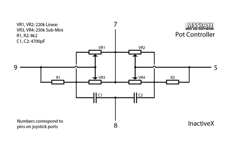
Re: C64 Pot Controller - New Circuit (41 replies, posted in Commodore Computers)
R1 and R2 are 8k2.
Theres a tiny bit more info to pick thru here:
http://www.mssiah-forum.com/viewtopic.php?id=1935
http://www.mssiah-forum.com/viewtopic.php?pid=15146#p15146 wrote:
You have a certain lee-way with the values of the pots and caps. The important one to get right on is R1 and R2 (8k2). This affects the taper of the pots, and 8k2 is the ideal fit, regardless of what the other components are rated at.
The 100k pots are a little on the low side though. If you get some higher R ones that might be better (you may find that the trims' sweet spot is near the edge of the dial the way you have it now).
This was in response to someone asking if 2200pF caps were ok to use. The caps reduce jitter, but too high and you'll have delayed response of the knobs.
60 Dec 8, 2019 9:08 pm
Re: C64 Pot Controller - New Circuit (41 replies, posted in Commodore Computers)
neonlike wrote:
Sorry to bump an old post...
Is this the diagram in the OP's post?
Does anyone have a clear image of the diagram and a correct list of components (including values)?
Thank you
Check page 2 of the thread. Several people made different visualization of the schematic.
61 Dec 8, 2019 8:27 pm
Re: C64 Pot Controller - New Circuit (41 replies, posted in Commodore Computers)
akira^8GB wrote:
Well it's me again.
I am trying to get the parts and I am having problems sourcing electrolytic 4700pF capacitors. Can I use ceramic ones, the ones shaped as little discs? I read somewhere they might introduce noise to analog signals so they might not be the best thing to use...
I try not use ceramic within the audio signal on boards I sell, but if its an analog envelope or lfo, or decoupling then its fair game. The "noise" it introduces is actually quite trivial.
I would recommend film caps for smaller values.
https://www.taydaelectronics.com/4-7nf- … citor.html
Also note that 4700 pico = 4.7 nano = 0.0047 micro.
EDIT: nice, I thought the new post wa on page 1. ![]() Nevermind me...
Nevermind me...
62 Dec 5, 2019 12:50 am
Re: Really expensive (but super cool) Megadrive anyone? (11 replies, posted in General Discussion)
Apeshit wrote:
Also, Nintendo Age, as we knew it, is defunct.
Geez, I had no idea. Guess I haven't been around.
63 Dec 4, 2019 8:32 pm
Re: Really expensive (but super cool) Megadrive anyone? (11 replies, posted in General Discussion)
catskull wrote:
Apparently the cartridge isn't actually using the YM2149 chip, just streaming compressed audio. Still cool, but could have been cooler. I ordered one because I'm intrigued with the cartridge!
Aww... ![]()
If thats whats cool now, lets make a portable AM/FM tuner for Famicom. xD
64 Dec 4, 2019 8:29 pm
Re: Really expensive (but super cool) Megadrive anyone? (11 replies, posted in General Discussion)
As far as I'm concerned, they're a legit and boutique getup. Very high end, quality manufacturing. I know some people with their products.
My guess is that they make their stuff wherever and then only sell through retailers in multiple countries, not out of their garage. ![]()
I don't think there is any grounds for suspicion.
Honestly this isn't the place to get the best discussion of these. A little to high-brow for our ilk. If you want good opinions, talk to some of those purists on Nintendo Age or something.