bit 9 wrote:The Teensy in the photo is one I've absolutely destroyed because the one I'm going to use needs to be salvaged from another build.
Call me crazy, but I think that Teensy is totally salvageable, if all you destroyed is the USB jack. Given thin wire single strand wire, a good iron, and some flux, and of course patience, you should be able to connect single strand wires to the resistors. That's your D+ and D- pins. If you want to live on the wild side, (or you messed up) you can even get rid of the resistors and connect the wires directly. This will violate USB spec, and offer slightly less protection of your chip and USB port, but will usually work. Ground and Vcc should be far easier to hook up, but you need to find the right place to connect +5V, in case Vcc on that board is actually the regulated 3.3V.
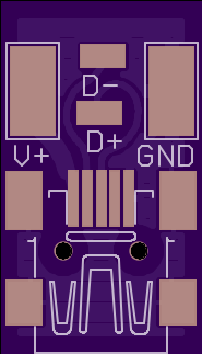 But that's only one side of the story (and conneciton). I designed these little simple minimal USB port adapter for random uses, which would be suitable here. Just glue this board down over the missing USB port and jump the wires over from board to board.
I may also have some comments about the project in general. If you're going to do this seriously, you may consider making your own board for the microcontroller, at least if you can have them assembled with a pick and place machine by the board house. That would give you more freedom to fit more stuff in less space in total than using a premade Teensy unit. SMD size: Like Benn said, if you're going to solder by hand, use 1206 resistors, though I think most people can get used to 0805 rather easily too. And to again echo what people have said, the board house will typically provide you with specifications and DRC rules. Nevertheless, stay a bit above the minimum width to avoid problems.
