bit 9 wrote:
Alley Beach wrote:

the arduinoboy needs some capacitors i think..

Only for the clock, which isn't included in trash80's original schematic.

What? I don't know of any Arduinoboy schematic where there's a capacitor on any clock line. I think what Alley Beach meant, and what you should preferably do, is to add a capacitor between power and ground in order to keep the power supply voltage stable. And, I would probably personally have designed the schematic to use SMD components, but that's just me. Oh, and in that case (and maybe even now) add a programming header.

bit 9 wrote:

What is the purpose of the copper sticker on the back of the PCB?

Most likely just to provide a lower impedance ground path to the full circuit, plus perhaps shielding, perhaps for regulatory reasons. Belts and braces type of stuff.

bit 9 wrote:

Does the cap with unregulated power directly over the amp (C2) affect the audio coming out if it?

C2 and (I think from the schematic) C9 are connected from the respective amplifier output (pins 12 and 15) to ground, and provide some high frequency attenuation, so yes, they do affect the quality of the sound. (In the neutral meaning of the word quality.)

bit 9 wrote:

What's the significance of the six soldered holes near the top of the board?

The Gameboy Wideboy development unit gives a hint. This development unit has a dummy piece for the Gameboy, with no CPU, but buttons and an LCD. Those same holes exist there, but have silkscreen marked out. They are intended for capacitors, for some overshoot limiting or so. However, they are not populated even in this dev unit.

bit 9 wrote:

Why are there leads from the screen socket going nowhere?

Those are test pads for probing the video signals. On older DMG motherboards they are exposed to so you can probe them, but they remain in later revisions as vestigial traces. I would recommend exposing them if anyone for any reason want to probe the video signals.

bit 9 wrote:

The rectangular stop masks on the back are for grounding the screen’s PCB, what are the circular ones for?

You may have been looking too long at the schematic compared to a real motherboard. wink
The round ones are for attaching the copper sticker.

bit 9 wrote:

How dost one safely remove the DMG’s screen?

The connection point to the PCB is mechanically fragile. You want to make sure that all solder is molten before you lift it. Your best bet is likely hot air, but be very careful to not damage the LCD or LCD ribbon interconnect.

bit 9 wrote:

How dost one safely re-attach the DMG’s screen?

With love and tender care. smile

bit 9 wrote:

Can anyone ID the parts on the power regulation aux board? (is this right?)

It should be about right, but good luck ever finding a suitable transformer new. You're likely better off designing a power regulator board from scratch.

bit 9 wrote:

Why are there jumpers (?) on the back of the screen’s board?

The LCD board, despite being double sided, does not have through-plated vias. So those are indeed jumpers. On a modern PCB, just replace them with a track going on the bottom, connected on each end to the other side with a via. Note that one of the links (the one with two end on the bottom side) is not an electrical link, but a mechanical placeholder for the LCD ribbon cable.

bit 9 wrote:

What would you want to change/add to the DMG’s circuitry to aid the musician/modder?

Prosound. A footprint for an LCD signal inverter for a biversion mod using a 6 pin dual inverter. Arduinoboy. Maybe replace the headphone amplifier with something more modern and less noisy. Maybe a rechargeable LiPo battery, assuming this can be done safely. If you want to get funky, an analog audio filter like http://www.youtube.com/watch?v=9KDI3UbW_3w.

bit 9 wrote:

Is there anyone on this forum that would be willing to work collaboratively on an modded PCB?

*raises hand*

bit 9 wrote:

Also, I don't actually know about the accuracy of the CPU/RAM pinouts and wouldn't know where to start. Can anyone corroborate this?

Should be about right, except maybe the naming of the display data pins, and the CLK? pin, which I believe isn't really a clock pin at all, but a gate signal specifying that there's bus activity.
467

(66 replies, posted in Trading Post)

Yeah, it should work. Either you did it wrong or the server hosting the image has disabled hotlinking.

The sav is not a ROM. It's a save file. It contains save data, and renaming it to .gb makes no sense. You need an LSDj ROM that you put side by side with the .sav, that has the same name but different file extension. So you might lsdj.gb and lsdj.sav. Then you open lsdj.gb in BGB, and it automatically finds lsdj.sav. You need an actual LSDj ROM for this to work.

onapokoya wrote:

(why did "f o o l" get changed to "cat"?)

Sorry, leftover from last year's April fools.

470

(15 replies, posted in Audio Production)

The first thing to check is which type of GB you're using and whether you've prosounded it. Those are the two main things influencing the noise floor.

http://www.herbertweixelbaum.com/comparison.htm

And of course, a crappy audio interface might add noise as well. Try recording silence from the audio interface with nothing plugged in and see how it sounds. Maybe you actually ought to get a new interface. (Especially relevant for built-in interfaces in laptops.) Yet another thing you may want to try is draw a spectrogram of the audio and look for the frequency of the whine, then use a very narrow eq to take that particular frequency out. This also assumes that the whine is at a fairly constant frequency. Not sure what capabilities Audacity would have doing something like that. I could upload pictures and an audio example of how to do this in Adobe Audition.

http://gbdev.gg8.se/files/musictools/PixelH8/
-> pixelh8-fixed.zip

Have you checked if it matches a PSX memory card? Just a wild guess.

AT90S2313 is the MCU model number. 0141 is the date code. (YY/WW.)

473

(3 replies, posted in Bugs and Requests)

It means your inbox i full or nearly full and that you may need to delete messages to be able ot receive any further messages.

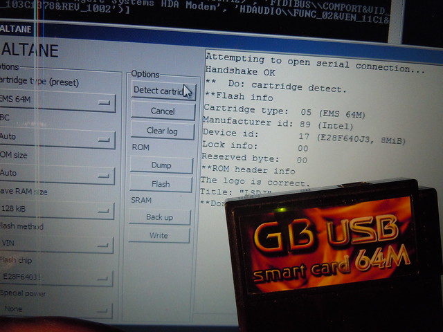
No. That's a way of categorizing special functions on mapper chips that otherwise behave like a standard MBC5 or similar. For example, Nanoloop One is listed as its own MBC in the MBC list because it's using a special command set for switching between banks. EMS on the other hand behaves like a standard MBC when as far as the switching between banks is concerned, so the standard bank switch code is used when flashing. However, it also allows for multi-ROM functionality, which is then listed as a special power. Funky name, yes.

Jazzmarazz wrote:

I see two bank support. Is that a software or hardware trick?
What can it do with the Mega Memory card?

Just so I'm not giving any wrong impressions here. I have not figured out a way to switch between the two pages from the cartridge bus. This may be impossible, even. The flasher will just flash whichever page is currently active, probably page 2 for the most part, knowing how these carts works. tongue But apart from that limitation, EMS 64M flashing works beautifully.
Note however that you have access to multi-ROM functionality within one "page", given an appropriate menu ROM, so only being able to flash one page may not be such a big loss.

MMC supports is not yet implemented, but the plan is to fully support reading and writing from the cartridge.

Teaser time!

Here's Rolf's boards, and my mod to it: http://gbdev.gg8.se/files/schematics/DMG-Rolf/

Rolf's board didn't aim for a perfect reproduction, but expandability. Are you planning on sharing the actual schematic and board files? If so I can host them in that snazzy file area of mine along with Rolf's schematic.

If you use IRC, try #gbdev on EFNet.

Ok, let's list them.

Krikzz project.

There's another project whose creator wishes to remain anonymous for the time being, to avoid being flooded with questions about when it will be done. (No, I'm not involved in this project.)

A DIY project. Unclear what happened to it. http://chipmusic.org/forums/topic/13256 … for-gbgbc/

Jose Torres' project. Vaporware. Nothing to see here, move on. Trust me. http://hackaday.com/2009/08/28/usb-gameboy-cart/

This project, which communicates directly with an SD card. Can't exactly be defined as an SD cartridge, since it requires a connection inside the Gameboy in it current rendition. http://zdoom.ic.cz/gameboy.html

480

(6 replies, posted in Nintendo Handhelds)

Just checking, are those the 64M USB ones, or the older blue 32M non-USB ones?