pselodux wrote:

This is an interesting idea.. if you use something super reflective (ie. moreso than the film from a stock gameboy) would it mean you could see your reflection in it?!

You already can, even if faintly. If you hold your finger to a stock DMG screen and look closely, you'll see two reflections, just like on a regular mirror btw. One from the front of the glass, and a fainter one that is slightly offset, from the reflective layer. For best effect use a spotlight pointing to the area you;re looking at.

98

(3 replies, posted in Nintendo Handhelds)

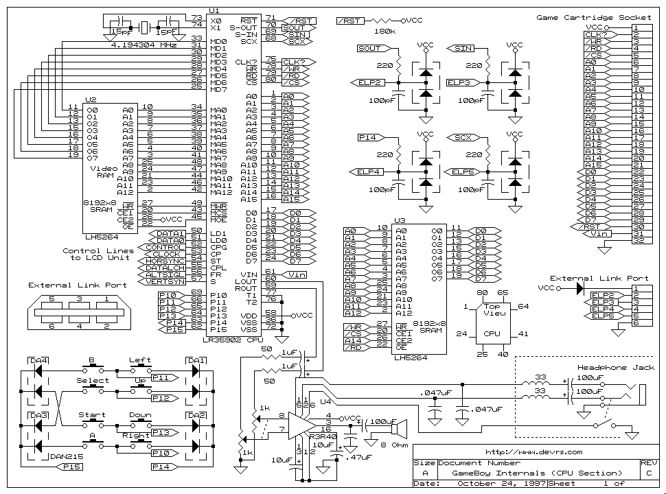
You've done your research. Well done. Indeed, left and B share the same physical input on the CPU. If you insert or remove the ribbon cable while the DMG is on, and misalign the cable ever so slightly so this connection is short circuited to the next one, which happens to be a -19 V supply for the LCD, the left/B input on the CPU is permanently damaged. Moral of the story, always turn off the DMG before inserting/removing that connector.

Are you absolutely sure the B button still works? There's really no way the left button could be broken without the b button unless there was some kind of problem, like a broken trace, around the area before the the B and left traces meet up on the LCD board. But then it wouldn't make sense that the button would start working, unless you accidentally rejiggered something in the process. If indeed it's an intermittent problem with the LCD board button connections, the good news is that you should be able to fix it with a little bit of soldering.

If it turns out to be a CPU problem, don't throw it away. You could give this 'boy some new life as a LSDj slave mode player, or MIDI synth.

As for probing, these are the relevant signals on the ribbon cable:

Pin 04 Left & B buttons
Pin 05 Button Diodes 1 & 2 (directionals)
Pin 06 Down & Start buttons
Pin 07 Up & Select buttons
Pin 08 Right & A Buttons
Pin 09 Button Diodes 3 & 4 (buttons)

The way it works is you have to put the negative (black) multimeter probe on the "diode" connection and the positive (red) probe on the other corresponding connection. As you press a button those two connections will short. Since there is a diode in series, you need to use the diode mode rather than the resistance mode, and beeping may not work so you might have to look at the multimeter screen for a readout instead.

Schematic for reference:
Site5, but currently planning to move the site because of this discussion.

jeff: Currently, chipmusic.org runs on a Site5 account. There's ssh access but I believe it's managed hosting, so no access to root or global server config. According to their FAQs, LE is not supported at this time. If you have information on how to get LE working on Site5 in particular I'd be willing to listen. But otherwise, switching to a different provider is unfortunately something that neither me nor Tim has the time to do atm.

Have you checked that you didn't swap ground and signal for either of the outputs? I probably would have used blue wire for both the grounds and red wire for both the signals to avoid this mistake.
You're tapping SID 1's output directly from the chip. Do you have any kind of circuitry between it and the output jack? You should ideally have a transistor circuitry like the one on the board, or just reuse the one on the C64 motherboard. Or at the very least a 1k resistor and 10 uF capacitor (example values) in series to protect the chip and remove the DC offset from the signal.

102

(3 replies, posted in Releases)

Y'all are all wrong! The problem was that the links started with an upper-case H. This made the URL parser turn this

Http://www.example.com/example

into this:

[url=http://Http://www.example.com/example]Http://www.example.com/example[/url]

No colon was omitted on the part of the poster. This was done by the browser.

At the request of nordloef, I modded Carillon to include a waveform editor for ch3 in the ROM. To try it, download carillon-wf.zip from here. Bug reports and feature requests are accepted.

http://gbdev.gg8.se/files/musictools/Aleksi%20Eeben/

104

(17 replies, posted in Motion Graphics)

Calavera wrote:
nitro2k01 wrote:

Sure it's not just a random troll?

Nullsleep's troll account.

But do you have any reason to believe that other than the name?

105

(17 replies, posted in Motion Graphics)

Calavera wrote:

(This is nullsleep's alt account, fyi)

Sure it's not just a random troll?

106

(45 replies, posted in General Discussion)

You know what, changed my mind. The sexist stuff (and following discussion) is now moved to the graveyard and I gave Martin a two week ban.

No, probably not normal. Can you do what I suggested above with regard to that? Please check during the startup sequence that it cycles through every LED and that none are missing from the sequence. Then also press the mode button and see if that does anything.

Correct, that's the 5V which is normally unconnected if you're using external power.

Also the picture of the link connector can be kind of confusing it's showing the link connector as seen on the Gameboy, which would mean that the connector would be mirrored if you looked at the plug. BUT that image is incorrect and you have to pretend that you're looking at the actual plug on the cable instead.

Try this. Just to confirm, this assumes in both cases looking at the connector from the front.

The changes from the pictured wiring, in words:
On the link connector:
* Move the green pin back on the connector back to where it was originally.
* Move the red pin to where you just removed the green pin from.

On the DIN5 connector:
* Move the blue wire to the outermost pin, opposite side of where the red one is.
* Move the green wire to where you just moved the blue wire from.

Assuming I didn't mess up, that should work.

Can you tell me exactly which pin on the plug you swapped from and to where? And also where on the board you connected that wire?

As for the status LEDs. They should do a blink sequence for testing on startup, then light up only one LED (when idle) indicating the mode. Carefully check if any of the LEDs never light up during the startup sequence. It's possible you connected one LED reverse or otherwise incorrectly and that that LED happens to be the active mode. You should also be able to get around this by trying to press the button to switch modes and see if any LED lights up. Something else could be wrong but start with that.

That mod is only necessarily if you want to power the Arduinoboy through the link cable instead of using external power. Choose one or the other. Also, you need a ground connection over the link cable. If you used the ground pin for the pin swap, you need to connect ground through the shielding of the cable. If you used the data out pin, this is not a problem but then of course you're losing the MIDI out capability.

As it is now, you're backfeeding power into the Arduinoboy through the data pins of the link port, which is what is making the backlight light up dimly. This would happen regardless of the pin swap, though.

Just to clarify, I didn't make Pushpin I just modded it.