210 Apr 1, 2012 10:19 am
Re: LSDJ and You: The Tumblog (70 replies, posted in Nintendo Handhelds)
It works on the pulse and noise channels too. Say you're running a table on the pulse and you want to change the note without retriggering the table, just delete the instrument. Note changes, table (or envelope) continues uninterrupted.
I had no idea it worked with other channels, I thought it was just limited to wave!
211 Apr 1, 2012 10:08 am
Re: Arduinoboy mGB mode LED question (6 replies, posted in Nintendo Handhelds)
Link goes to a 404, heads up.
212 Apr 1, 2012 9:54 am
Re: LTC 1799 Precision Clock Kit (12 replies, posted in Nintendo Handhelds)
I would much rather lose the original headphone jack, its not pro sound.
Alternatively I also have a decent amount of space on the right side of the bottom shell.
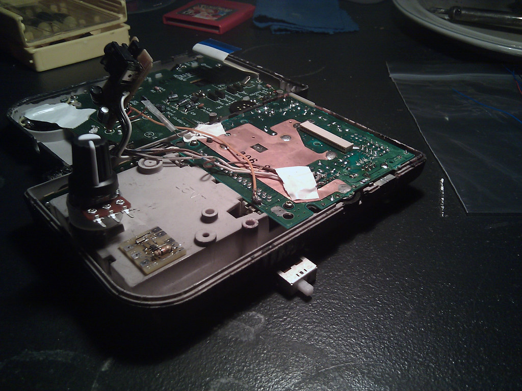
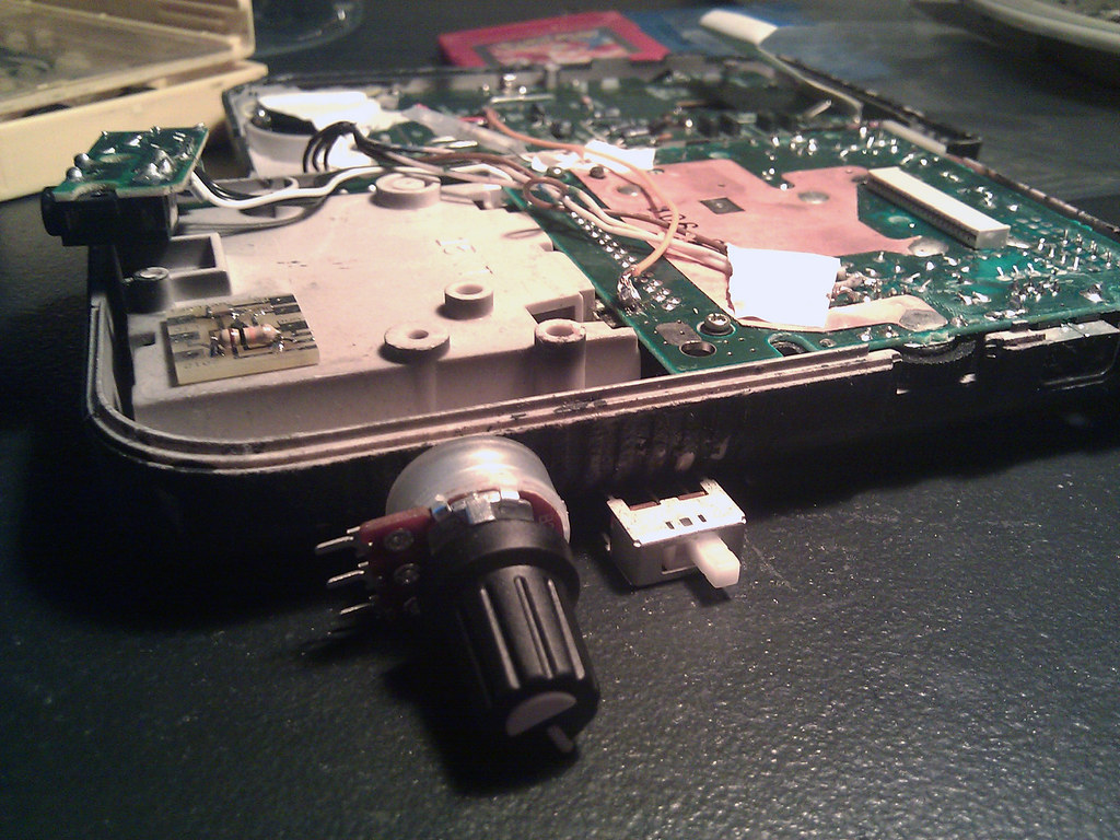
Here are the 2 layouts I could think of that don't remove the speaker.
1: Remove of the stock headphone jack PCB and small plastic molding to hold the PCB in place
2: Dremel bottom shell to make room for knob and switch (Kinda odd placement though...)
If it be mandatory I must remove the speaker it will be done!
213 Apr 1, 2012 12:03 am
Topic: LTC 1799 Precision Clock Kit (12 replies, posted in Nintendo Handhelds)
Hello once again fellow chip-tuners, I just received my order for a LTC 1799 Precision Clock Kit from getlofi.com. I'm very excited for this mod, there is only one problem. Where am I going to find the room to mount this sucker?
I was thinking about removing the stock headphone jack board including wires and placing it below the start and select buttons.
I just want to double check with you guys that everything will still be functional if I do this kind of procedure.
214 Mar 30, 2012 7:29 am
Re: Abducted By Sharks - Hammerhead (4 replies, posted in Releases)
Dido
This is fucking great man I dig it! A lot!
215 Mar 29, 2012 1:48 pm
Re: D-pad left direction suddenly stops responding.. (12 replies, posted in Nintendo Handhelds)
Its funny you mention that, a few hours ago I had already begun the process of interchanging the bottom board hopefully to find a fully functional CPU.
I then put in the flashed cart as you mentioned and to my surprise you were absolutely correct! The problem lied in the bottom PCB CPU unit, not the top PCB ribbon cable which I had presumed.
The 'Left-test.gb' ROM works beautifully for LEFT & B button diagnostic purposes.
nitro2k01 you might want to inform future testers that it is intended for screen to freeze at the 'NINTENDOr' logo after the ping, until either LEFT or B button is somewhat function and activated. I didn't quite know really what to expect and was considering that I may have done a bad flash or it was a cart related problem.
Although my inverted polarization screen actually turned white, which kinda threw me off for a few minutes.
FUNCTIONALITY!
1 Gameboy down, 2 more to go wish me luck!
-------------------------------------------------------------
On a side note:
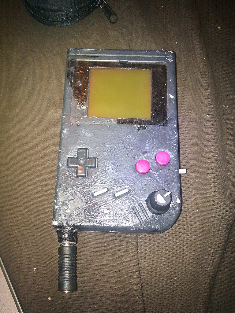
Does anyone know where I could locate a tutorial / inform myself on how I "should" go about painting a DMG01?
What type of paints works best for a matte finish, while still withstanding minor scratches and such or how to add a protective sealant layer.
Spray paint, acrylic paint, paint markers???
216 Mar 29, 2012 3:05 am
Re: D-pad left direction suddenly stops responding.. (12 replies, posted in Nintendo Handhelds)
Tested the rom. It is suppose to just chill at the boot logo correct?
Neither hitting B or Left would give me a darker screen.
Heres a CPU chip if it helps...
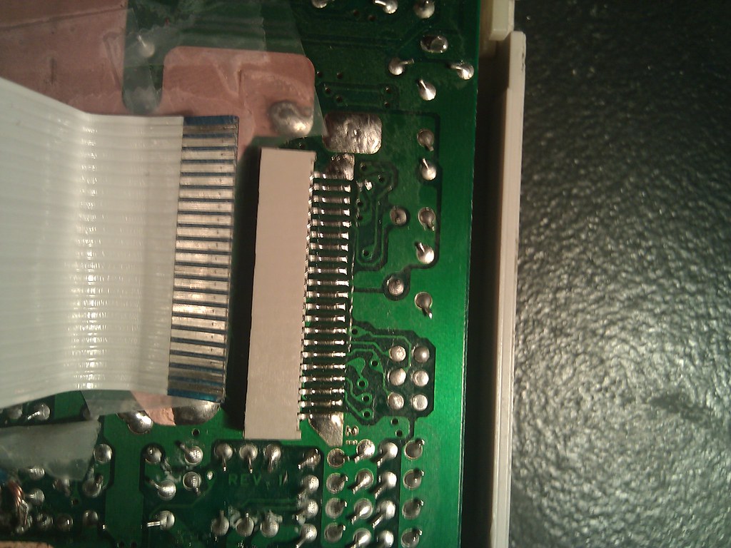
Does anyone know if it is realistically possible to transplant a ribbon cable that connects the two PCB's together?
There is two huge ass globs of solder on the sides securely attaching it to the top board which makes me think that the pins would come off in a somewhat clean manner.
217 Mar 29, 2012 1:49 am
Re: D-pad left direction suddenly stops responding.. (12 replies, posted in Nintendo Handhelds)
I will test the rom in about an hour, at the moment 2 of my DMG's are getting paint jobs and its still wet.
The mother board revision is DMG CPU 08
218 Mar 28, 2012 11:19 pm
Re: D-pad left direction suddenly stops responding.. (12 replies, posted in Nintendo Handhelds)
219 Mar 28, 2012 10:56 pm
Re: D-pad left direction suddenly stops responding.. (12 replies, posted in Nintendo Handhelds)
yes you may
220 Mar 28, 2012 10:55 pm
Re: D-pad left direction suddenly stops responding.. (12 replies, posted in Nintendo Handhelds)
FUCK ME!!!
As a matter of fact the B button also stopped working ![]()
Third broken Gameboy in the past 3 days.
Anyone have any clue as to a fix for this?
221 Mar 28, 2012 10:01 pm
Topic: D-pad left direction suddenly stops responding.. (12 replies, posted in Nintendo Handhelds)
The board is clean along with the rubber gasket. I don't see much room for error here. Its only the left all other directions work fine.
Nothing is seeming to go my way right now with in the gameboy hardware department.
Any ideas?
222 Mar 28, 2012 7:38 pm
Re: In need of a gameboy hardware guru, Dot matrix problem (7 replies, posted in Nintendo Handhelds)
PM'd.
I just want to say, I can't thank you gentlemen enough.
I'm glad to have found such a fantastic chiptune forum community, you guys are fucking fantastic!
223 Mar 28, 2012 7:09 pm
Re: In need of a gameboy hardware guru, Dot matrix problem (7 replies, posted in Nintendo Handhelds)
Wow! THANKS KINETICTURTLE SO MUCH!!! Very nice detailed post, I can finally stop racking my brain with troubleshooting for hours upon end.
I figured the second one photo'd was completely cached nada worries though. I don't know how I feel personally trying to solder the thin wires to the board contacts then to the connector socket. You would be correct this is really my first soldering project, but mostly its just because I've solder and soldered over it again and again due to trial and error and lack of patience with this machine.
Now I still have a perfectly fine ribbon cable (like shown in first picture) connected to the sliced ribbon cable unit. How difficult would you presume it would be to make this kind of transplant? / Would I even be able to handle it without a big solder mess?
Out of extreme curiosity and interest how much would and 3 of you guy's charge for this kind of operation or just an entirely new screen PCB?
224 Mar 28, 2012 8:21 am
Re: In need of a gameboy hardware guru, Dot matrix problem (7 replies, posted in Nintendo Handhelds)
I uploaded photos and a demonstration video here : http://www.flickr.com/photos/78506184@N … otostream/
This is currently the first gameboy's bottom half with the second's front board installed, just to clear where this project is at right now.
