Why not just lower the input volume on your pc?
Stupidly simple as that... I turned down the input volume in Audacity and now it sounds perfect.
Thanks very much for the tip SketchMan!
chipmusic.org is an online community in respect and relation to chip music, art and its parallels.
You are not logged in. Please login or register.
ChipMusic.org / Forums / Posts by DogTag
Why not just lower the input volume on your pc?
Stupidly simple as that... I turned down the input volume in Audacity and now it sounds perfect.
Thanks very much for the tip SketchMan!
Hello guys!
I recently acquired a Pro-Sound modded DMG and I am using it to record my LSDJ tracks on my computer. My problem is that the pro-sound mod was made in a way that you can't change the volume with the pot, so it's fixed at (I believe) maximum volume. The thing is when I record it to my computer line-in, the software (Audacity) gets it, but too loud, enough to distort it badly...
So I would like to hear recommendations on what to do.
I have decided not opening the DMG to fix it myself, because it has other mods and a big deal of wires there... too much for a noob like me.
One thing I thought could be a solution is making a small volume pot out of the game boy. Say two female jacks, one for the line-in and one for the line-out with a potentiometer between them, all fitted in a small box.
Apart from that, I don't know if there's something I can do to avoid my computer software or sound card to distort the song due to its volume.
Any advice/suggestion is well received : )
Man it's awesome! I love the vocals on the first track ![]()
Where can one get a copy of that CD living in Spain?
¿Dónde fue? Soy español también. Por curiosidad : ) ¡Espero que fuera bien!
///
Where was that? I'm Spanish too. Just for the shake of curiosity : ) I hope it was cool!
Packages arrived and everything is in perfect condition and as described by the other part. We've left mutual positive feedback in the correspondent thread. This can be closed. Thanks!
One thing you could do is if you have a spare GBA SP you can use its speaker, cutting a little of the housing in your GBC so that the SP speaker fits in there. It worked for me! : )
Traded with Krubbz. Now we are both waiting for the packages to arrive.
Hey guys.
I finished the simple APC, and wanted to share the result with you:
http://www.youtube.com/watch?v=7Jrn9SLX … redirect=1
I can't wait to have some spare time (actually I'll need plenty really xD) to try the mod. I'll make it from scratch, so that when I finish it, I'll have a simple version and then the one with the sequencer.
Thanks everyone for your help!
1 ... 2
3 ... 4
5 ... 6Connect 1 and 6,
connect 2 and 5.Wires go to 1, 2, 3 and 4.
After thinking it through... I understand! : D
Thank you very much! For a novice in electronics like me this tiny things are of much help.
I'll let you guys know whenever I have news. I'll try to build this thing relatevely soon, depending on how much spare time I can find.
Thanks to everyone who's replied : )
@ashimoke Thank you for explaining! I can get one of those locally, didn't know they were the same as standard 6 pin switches. Still, how would the wires be connected in a 6 pin switch? In the pic they only use 4, and it confuses me.
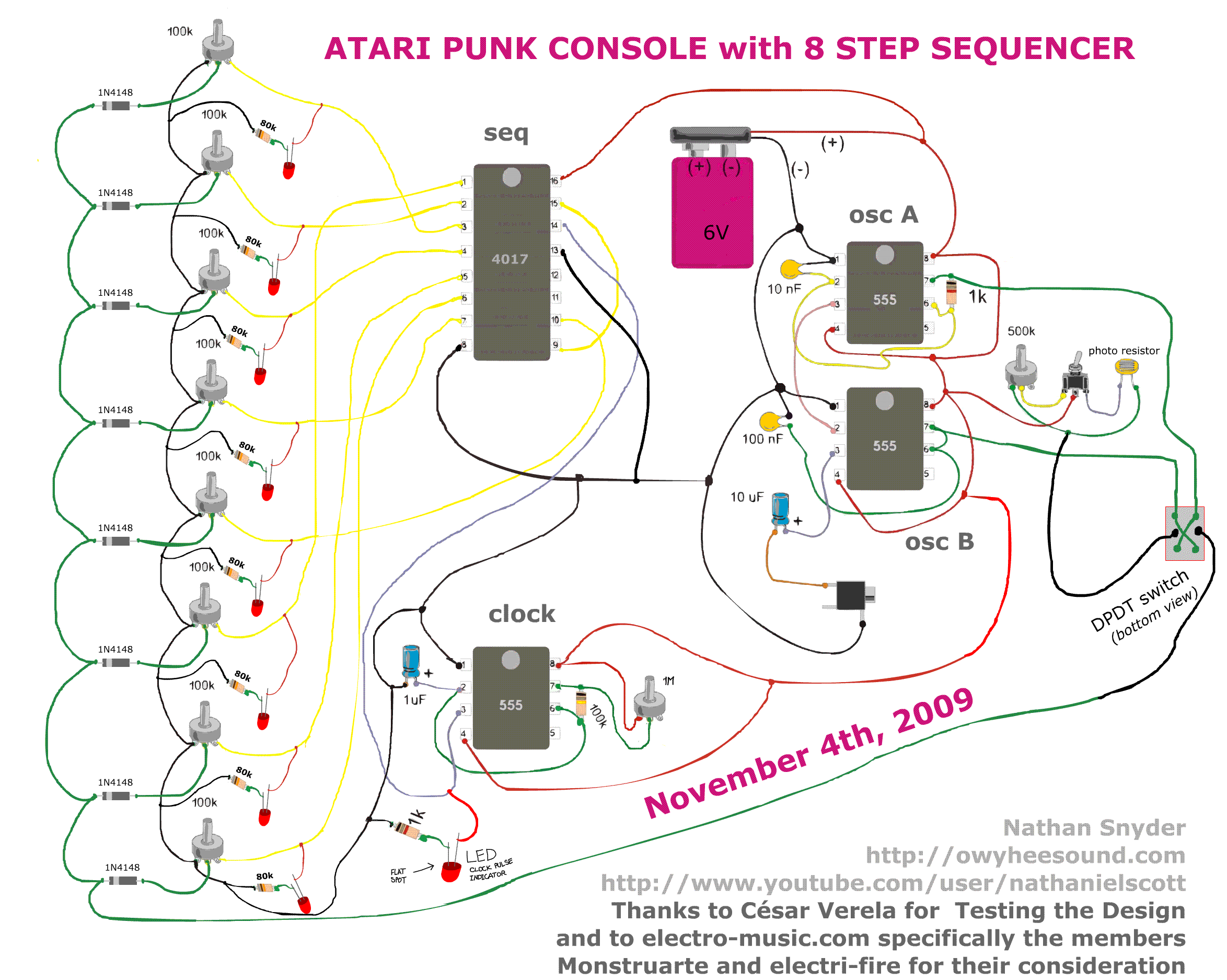
But can't it be replaced with a regular "stick" switch? And I don't really get what the DPDT switch is doing there... Any idea?
After a lot of research, I've found a clearer schematic of the mod:
Link: http://owyheesound.com/img/atari_punk_console.png
And there's a problem there. I don't exactly know what the DPDT switch is doing there, so don't know how could I substitute it. Around here it's impossible to find one of those. Someone?
By original I mean the one you refered to in your first post.
Got it now. Everything makes sense. The only thing I'm still asking myself is why those diodes instead of regular LED's? As I said, I like the LED's turning on and off.
I'll probably first make up the APC and whenever I find more time I'll join it with the step sequencer : )
Sorry ashimoke but I must be missing something. Which schematic is the "original schematic" you are meaning? I can't find any diodes or switches in the schematics you've posted so far...
And why don't need the LED's? I liked the lightning dance xD
What I don't understand is how the output should be connected. Apparently there are 3 pins and only one and ground connected. Should that be enough?
Thank you for that schematic ashimoke! So basically the wire connecting to ground after the 1K resistor connected to pin 2 of the APC should make it?
And a stupid question added: Shouldn't those LED's have a protective resistor?
Thanks for the help!
EDIT: Got the jack thing! Thanks!
This is not the exact schematic I was looking for, but for a standard atari punk console it does seem to work:
http://blog.makezine.com/2011/09/13/col … k-console/
The only thing I don't understand here is how the output jack is connected. I suppose that in this case it's a stereo (though I think mono should be enough?) but I don't get the connections looking at the schematic. Any help?
ChipMusic.org / Forums / Posts by DogTag