Another thing to keep in mind when emulating a NES controller by recycling the controller cable, is that you will need two extra resistors to make it work on a PAL NES:
34 Jul 2, 2014 9:44 pm
Re: Options to MIDI Sync the NES? (54 replies, posted in Nintendo Consoles)
yogi wrote:
You know, I have been kicking around the whole issue of 'the cable'. Finding a source of NES cables is like impossible, so that leaves recycling old (new ?) controllers or extension cables. I had noticed at INL's site he has CD4021 pulls from his USB mods so he may have cables also ( will have to ask him).
But then I was thinking of a internal mod with just a ribbon cable to the port 2 motherboard header. Downside is you can't move the interface to another NES and may interfere/disable a GamePad on port 2. For my case atm, I have a cable setup for prototyping but once it's done, I think I'll do a internal install. Would also cut down on extra gear, like in your case.
On a side note about the cable, you can't solder the wires in the (original) cable, so you have to use crimp connectors. They used a copper foil/nylon conductor, like a lot of headphone cables do. Don't know about after market GamePads.
Just a thought
Yogi
I went through the same thought process when designing the FamiiDI shield, and that's why I decided on a standard DB15 connector (DA15 if you want to get technical) - one of my NES's has the DB15 mounted and wired directly to the Expansion Port pins on the motherboard, like this:
http://www.retrorealities.com/retroreal … hp?tid=190
The other big advantage of this is that because the connector follows the Famicom Expansion port standard I can hook up all the funky old Famicom Expansion peripherals!
35 Jun 28, 2014 12:18 am
Re: Options to MIDI Sync the NES? (54 replies, posted in Nintendo Consoles)
+1 to everything yogi said, just have one comment to make...
yogi wrote:
The other issue is the connection to the CD4021 in the GamePad. The Buttons are active low logic; I.E. when 'Open' a 10K R pulls the pin high, Closed to GND.
The 'resistors' (actually just lumps of 'resistive material') in a NES GamePad are actually 38K, not 10K. Here's an old Ben Heck article with some more detail:
http://www.extremetech.com/extreme/7468 … ent-system
and here's an example of 10K resistors not working in a project:
36 Jun 26, 2014 8:47 pm
Re: NES and SNES. Can they put there differences aside and work together? (11 replies, posted in Nintendo Consoles)
nintendro boy wrote:
I agree that an external beat clock would
definitley be the ideal setup. Do you know of any midi interfaces for the SNES. Iknow I've read that the development kits came with a midi in, but other that I'M don't think I've seen a snes midi input.
Just as you can use a NES controller on a SNES:
http://www.youtube.com/watch?v=du9yco1zOeo
You could also use FamiiDI as a MIDI interface to the SNES - that's the easy part! The difficult part is creating the software for the SNES, as yogi says...
37 Jun 26, 2014 11:49 am
Re: NES and SNES. Can they put there differences aside and work together? (11 replies, posted in Nintendo Consoles)
...here's half the solution:
http://chipmusic.org/forums/topic/13101 … amislayer/
You just need a SNES / .SPC version of something like FamiSlayer to form a happy marriage!
38 Jun 21, 2014 4:23 am
Re: SELLING NES STUFF (1 replies, posted in Trading Post)
Hey Nick, been two months now since the auction and not sure my E-Mails are getting through to you Re: the missing-in-action Four Score?
39 Jun 5, 2014 10:46 am
Re: pulsar sync with pulsar (9 replies, posted in Nintendo Consoles)
meanwun wrote:
I'd love to have an mctrl, but I value my marriage so a sub $50 option has to be explored.
40 Jun 1, 2014 9:59 pm
Re: DMG/Pocket video capture with Arduino or Teensy? (244 replies, posted in Nintendo Handhelds)
Jazzmarazz wrote:
uXe wrote:...are those pins available on the board though? and is there software library support for two SPI ports?
Another option which does have support for two SPI ports is the good old Maple Mini, and it looks like they can be found pretty cheaply on eBay...
Thats pretty neat, but you utilize port manipulation?
Of course - jump to Chapter 9 on GPIOs:
http://www.st.com/st-web-ui/static/acti … 171190.pdf
or even program in assembly if you like:
41 Jun 1, 2014 11:10 am
Re: DMG/Pocket video capture with Arduino or Teensy? (244 replies, posted in Nintendo Handhelds)
rvan wrote:
Reading the Freescale Reference Manual, it turns out that the Teensy's chip does have two SPI ports. We may yet be in luck...
...are those pins available on the board though? and is there software library support for two SPI ports?
Another option which does have support for two SPI ports is the good old Maple Mini, and it looks like they can be found pretty cheaply on eBay...
42 May 10, 2014 4:12 am
Re: MGB in a DMG case (26 replies, posted in Nintendo Handhelds)
Would help if someone explained why instead of just "Nope, sorry".
Take a look in the lower-left corner of the DMG schematic and you will see that the buttons use a matrix of diode arrays (4 arrays of 2 diodes each) and that the buttons don't all share a common signal the way that the common-ground PCB kitsch is selling does:
I can't for the life of me find a schematic for the Pocket, but looking at the board itself it looks like it uses two diode arrays instead (2 arrays of 4 diodes each?):
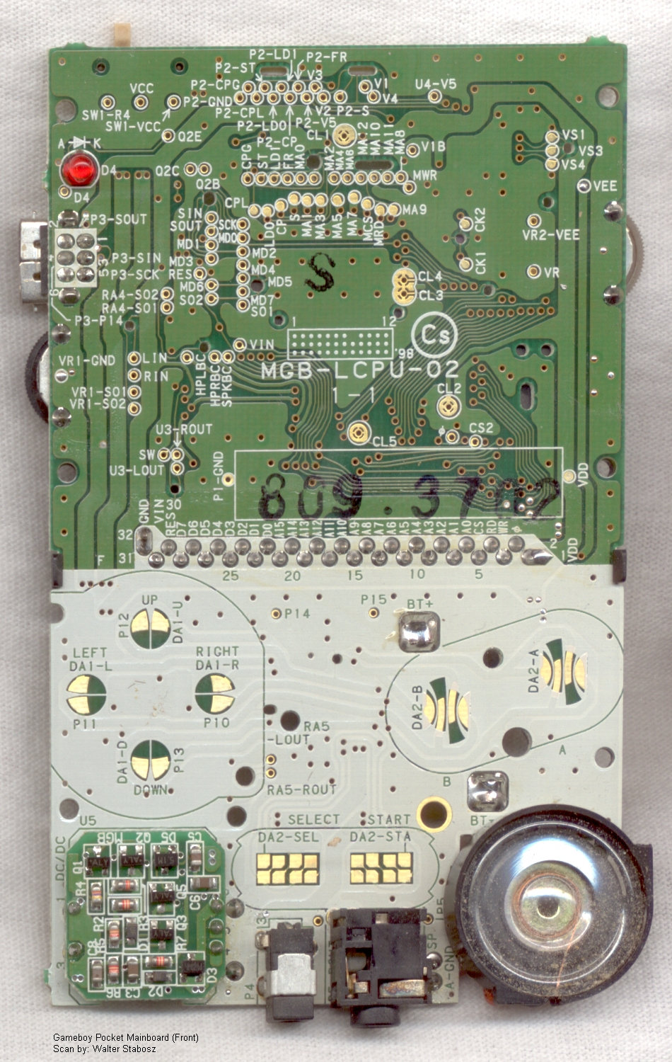
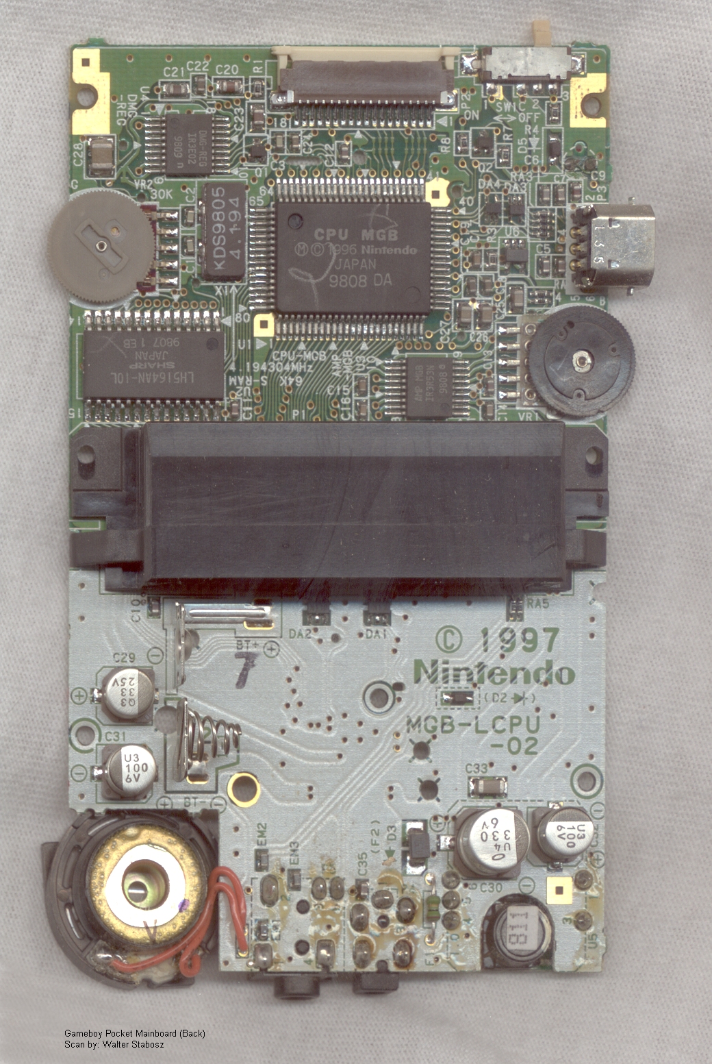
The common-ground PCB would work with a GameBoy Color though! Here's the button portion of the Color's schematic (from http://www.docstoc.com/docs/48266995/CGB-Service-Manual):

43 May 8, 2014 11:42 pm
Re: DMG/Pocket video capture with Arduino or Teensy? (244 replies, posted in Nintendo Handhelds)
friendofmegaman wrote:
Basically we need some solution that is clocked by LCD CLOCK signal...
the point of the SPI approach is that it is clocked by the LCD clock...
if you want some more ideas for getting those signals into the PC then spend some time here:
44 May 8, 2014 1:14 am
Re: DMG/Pocket video capture with Arduino or Teensy? (244 replies, posted in Nintendo Handhelds)
rvan wrote:
friendofmegaman wrote:Let's also get back to Flashing LEDs solution - there he used 2-SPI bus uC. We could try that. Although I'm not sure we'll be able to send data to PC at the necessary speed...
Getting the data into the microcontroller would still be a significant step forward. What are good options on cheap microcontrollers with two SPI buses?
Here's one:
http://www.digilentinc.com/Products/Det … IPKIT-CMOD
"SPI: Synchronous serial port. Pin 24 (SS), Pin 35 (MISO), Pin 25 (MOSI), Pin 16 (SCK). This uses SPI1 on the PIC32 Microcontroller. SPI2 is implemented as Pin 33 (SS), Pin 36 (MOSI), Pin 32 (MISO), and Pin 17 (SCK). When using the chipKIT Cmod with MPIDE, the SPI ports are accessed using either the standard chipKIT SPI library or using the Digilent DSPI library. The standard SPI library supports access to a single SPI port, SPI1. This is accessed using the SPI object.
The DSPI library supports access to both SPI ports. The DSPI0 object class is used to access the default SPI port, SPI1. The DSPI1 object class is used to access SPI2."
or you could just adapt Craig's source with the same board he used:
http://www.mattairtech.com/index.php/mt … board.html
(Edit: or a cheaper alternative? http://www.mikroe.com/mikroxmega/)
BeagleBone Black is supposed to have two SPI ports but a lot of people have reported trouble getting that working...
45 May 7, 2014 3:19 am
Re: DMG/Pocket video capture with Arduino or Teensy? (244 replies, posted in Nintendo Handhelds)
...or try PWM for the clock? Also, don't forget that even though the Teensy 3.1 is 5V tolerant, it only outputs 3.3V - which the GameBoy CPU may or may not like?
46 May 7, 2014 2:53 am
Topic: Analogue Nt (3 replies, posted in Nintendo Consoles)
...got a spare $500?! ![]()
47 May 7, 2014 2:43 am
Re: DMG/Pocket video capture with Arduino or Teensy? (244 replies, posted in Nintendo Handhelds)
friendofmegaman wrote:
rvan wrote:Post your code!
Sure, sorry guys I'm just loaded with work lately so things keep slipping off my mind. Here's the code (I know Jazz won't approve):
(Teensy only, won't work on Arduino)
Timer basedconst int pClk = 10; int clk_state = LOW; IntervalTimer myTimer; void setup(){ pinMode(pClk, OUTPUT); // I played with the timeout - no lucj myTimer.begin(tick, 0.125); } void tick(){ if(clk_state==LOW)clk_state = HIGH; else clk_state = LOW; digitalWrite(pClk, clk_state); }
Well, your tick routine could be simplified down to just a single GPIOx_PTOR command to toggle the pin state, but even then I don't think the interrupt is going to be fast enough to get back in time to toggle it again 125 nanoseconds later!
Maybe direct control over the clock would be easier to achieve by having the microcontroller generate a variable signal that can be fed into the standard variable clock mod chip (what the potentiometer normally does - not sure if it is wired as a voltage divider or a variable resistor though?) as well as start / stop control over the clock mod - at least then there would be predictability?
48 May 6, 2014 12:38 pm
Re: DMG/Pocket video capture with Arduino or Teensy? (244 replies, posted in Nintendo Handhelds)
Found this nice helpful document:
http://students.washington.edu/fidelp/g … Manual.pdf
Which shows that the OAM (Sprite) RAM is actually internal to the CPU:

So that puts a damper on the dual-port RAM approach, unless you use a hack to mirror $FE00-$FE9F into some 'unused' VRAM and read it from there... Still, there would be much fun to be had playing around with dual-port SRAMs and reading / writing the GameBoy's memory aside from video! ![]()
PS. the above PDF also provided this helpful diagram:
