friendofmegaman wrote:

Now I'm a bit confused are there two RAMs?

...at the risk of flogging a dead horse, the GameBoy Color and GameBoy Pocket only have a single SRAM onboard - so we'd be back to just the one dual-port SRAM to make it work:


http://console5.com/wiki/SRAM_64Kb:_8K_x_8-bit


http://console5.com/wiki/SRAM_256Kb:_32K_x_8-bit

Edit: unless the VRAM is built into the CPU? hmm

Edit: Yep... (from http://www.docstoc.com/docs/48266995/CGB-Service-Manual)

rvan wrote:

Also, either bandwidth or processing power becomes a major issue here. We would either have to send all 8 kB of VRAM Data (+OAM etc.) every frame, or do enough processing on the microcontroller to work out which data we do need to send (which would amount to the MAP every frame and tile data + OAM when the tilebank is changed).  This is assuming whatever is running on the Game Boy is using sprites in a normal way.  The situation would be quite different for things like the Game Boy Camera and possibly LSDJ.

This does not seem the most viable approach for a computerless screen capture solution, which I am interested in in particular.

The three-pixels-per-byte approach would still mean having to send 7.5kB every frame anyway, not that big a difference.

I do agree though that it would become a little complex, may be it could be an idea for the folks who are making plans to produce brand new motherboard PCBs to include dual-port SRAMs on them though! smile

rvan wrote:

I am still going to try out my shift register idea and Nitro's idea next, when I find the time.

Good to hear, looking forward to the results!

friendofmegaman wrote:

Now I'm a bit confused are there two RAMs?

...right next to the CPU:

friendofmegaman wrote:

I'm not sure actually... this fragment (talking about GB RAM):

OK, that is talking about the address bus, which is 16-bit (64K), those are the addresses you use to write to / read from many different components in the GameBoy, it is not a break-down of what is stored in RAM.

Yeah, like I said above, you would probably want TWO dual-port chips to be able to access both the Video RAM and the Working RAM - you are going to need access to the Object Attribute Memory to be able to draw the sprites...

friendofmegaman wrote:

1. Are these the same types of RAM? Do we need any adapters to plug it to GB?

The pinout isn't going to be the same, because it is dual-port so there are twice as many pins!

friendofmegaman wrote:

2. In my understanding the dual-port RAM replaces RAM in GB and connects (not replaces) to Arduino since the latter can work with external RAM is it correct?

Yes.

friendofmegaman wrote:

3. Let's assume we have steps 1 and 2 done, then to get the frame data we just need to read the corresponding region of RAM using Arduino's RAM API at the rate we want (may be 60Hz as screen, may slower if we are saving bandwidth) - did I get it right?

Yes.

friendofmegaman wrote:

4. Why do we need a piece of emulator code? Is it to get background and tiles data and build a 160x144 screen (or as you suggested 256x256 which is even better)?

A good explanation from http://gameboy.mongenel.com/dmg/lesson5.html

"The address space from $8000-$9FFF is video ram (VRAM). This area of memory isn't a plain linear collection of bytes that represent pixels on the LCD, rather this memory area contains building blocks that the LCD controller builds each screen with. Each of these 8x8 pixel blocks is called a TILE. The VRAM contains two major sections, one section for tiles, and another section for a MAP. The map area is a 32x32 byte array (1024 bytes) that makes up the Background Map, or BGMAP for short. The way the LCD draws a screen is this: it takes the byte value in the map area, and gets the corressponding tile from the tile set, and draws the 8x8 tile where it got the map byte from."

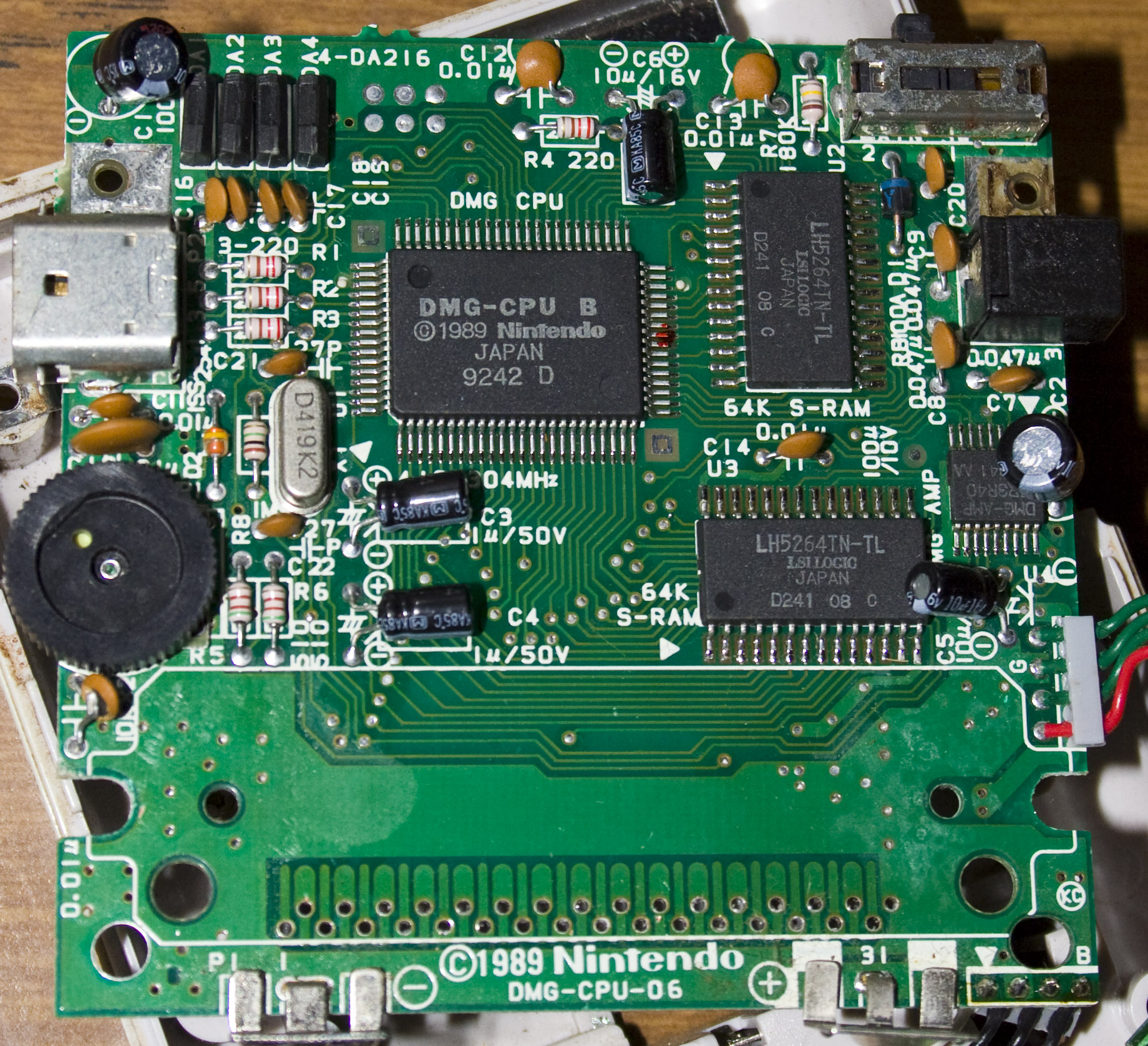
The only spanner in the works might be that the Sprite Attribute Table (OAM) is stored outside of VRAM - maybe physically separately in the other SRAM chip? in which case you'd need a second dual-port chip to be able to keep track of that as well - I haven't dug deep enough to be sure about that, anybody?

uXe wrote:

Actually, scratch that - just use a dual-port SRAM like this:

http://www.idt.com/products/memory-logi … l-port-ram

and there won't be any conflicts for the GameBoy and the Arduino to share the same memory!

...and then Batsly announces this:

http://chipmusic.org/forums/topic/14236 … interface/

Ha! Beautiful! big_smile

Jazzmarazz wrote:

Sounds legit, but also sounds like the most complex of ways to do this...hah...

smile seems really nice, and really straight-forward to me - the data is just 'there' in the shared RAM for you to read, being constantly updated by the GameBoy, without you having to make any effort at all! No crazy timing to try and match, no counting cycles, you would just read the data and assemble the frames...

For certain games you would even be able to mess around with constructing and viewing the entire 256x256 frame, instead of just a scrolling 160x144 window into it!

In fact, you could also experiment with writing into the shared RAM instead of just reading from it! smile

Actually, scratch that - just use a dual-port SRAM like this:

http://www.idt.com/products/memory-logi … l-port-ram

and there won't be any conflicts for the GameBoy and the Arduino to share the same memory!

Then just take the video generation routine of a GameBoy emulator and instead of having it generate video from a software emulation of the 'Boy, feed the real GameBoy's memory contents into and let it generate easily recordable video for you - voilà! big_smile

rvan wrote:
uXe wrote:

An Arduino Mega can directly address external SRAM as if it were internal

Good news.  But can the Arduino (or Teensy) access the RAM at 4.19 MHz, and when it is not providing the clock signal itself?  Clearly, we wouldn't have to read the RAM every single clock cycle, though.  Let's look more into whether the data stored in VRAM is in fact useful to us.

...it's SRAM (static) so it doesn't need to be clocked / refreshed the way DRAM (dynamic) does, here's a memory map:

http://gameboy.mongenel.com/dmg/asmmemmap.html

like I said, the question would be if it can be timed not to conflict with the GameBoy's access to VRAM - or maybe a second SRAM chip could somehow be piggy-backed to receive the same data from the GameBoy but allow reading by the Arduino without timing concerns...

rvan wrote:
Jazzmarazz wrote:

Does anyone know what sort of data is stored in VRAM? Is it simply active sprites, windows, etc? or might it be something useful to us?

This is an interesting idea.  The question is can we read the VRAM fast enough?

An Arduino Mega can directly address external SRAM as if it were internal:

http://andybrown.me.uk/wk/2011/08/28/51 … ga-design/

http://web.archive.org/web/201204190428 … garam.html

looks like some work has been done on Teensy support as well:

http://github.com/xxxajk/xmem2

the question would be if it could be timed not to conflict with the GameBoy's access to VRAM - or maybe a second SRAM chip could some how be piggy-backed to receive the same data from the GameBoy but allow reading by the Arduino without timing concerns...

60

(5 replies, posted in Nintendo Handhelds)

...some cheap cables aren't up to spec:

http://chipmusic.org/forums/topic/13398 … rduinoboy/

friendofmegaman wrote:

Aside from FPGA and SNES+SGB there's one more option that actually Craig from FlashingLEDs suggested - use a web cam, put it close to the screen and then on PC side extract the actual frame based on pixel colors. As crazy as it sounds it is a very interesting idea (a good example of out-of-the-box thinking). We need a cam, then front PCB (we can actually saw off the lower half to make it smaller, add some light (either backlight or simple LEDs). But that's theory, to be certain experiments are needed.... In the end it can be hacked into a very tiny device (as big as the GB LCD and as 'fat' as webcam allows, which on its turn too can be disassembled and 'flattened').

That definitely does sound interesting - but if you are going to go to that level of abstraction to record video from a GameBoy, why not just record the output of an emulator instead?

You could have an emulator running the same ROM / saves / whatever that you are running on your GameBoy, hook the Teensy up to the button contacts on the 'Boy and use it as a USB joystick to be able to control both the emulator and the GameBoy in your hands at the same time... you wouldn't even necessarily need a PC for the emulation / recording, a Raspberry Pi would be enough!

That said, I would still like to see rvan try the code I posted above with an oscilloscope to see the results...

friendofmegaman wrote:
uXe wrote:

...if you try this code, it should toggle the LED with every clock - ie. the LED should be illuminated on every second clock

And how do you tell how many times the LED blinked? A 10 000 000 FPS per second time lapse video? smile

Firstly, it is being triggered by the GameBoy clock so should only blink 2 million times a second in the version with interrupts, or 4 million in the version without.

Secondly, rvan's plan was to use a digital oscilloscope to compare the pulses on the LED pin with the GameBoy clock pulses to try and prove one way or the other if the Teensy is capable of at least reading the clock signal, apparently it didn't work with his original code, which is why I was trying to help with this code - but yeah, by all means break out the high-speed camera! tongue

uXe wrote:

...if you try this code, it should toggle the LED with every clock - ie. the LED should be illuminated on every second clock:

#include <WProgram.h>

#define CLOCK_PIN 23
#define OUT_PIN 13

void clock_ISR() {
    GPIOC_PTOR = B00100000;
}

int main() {
    pinMode(CLOCK_PIN, INPUT);
    pinMode(OUT_PIN, OUTPUT);
    attachInterrupt(CLOCK_PIN, clock_ISR, RISING);

    for(;;) {
    }
}

...or without toggling and interrupts:

#include <WProgram.h>

#define CLOCK_PIN 23
#define OUT_PIN 13

int main() {
    pinMode(CLOCK_PIN, INPUT);
    pinMode(OUT_PIN, OUTPUT);

    for(;;) {
        if (GPIOC_PDIR & B00000100)
            GPIOC_PSOR = B00100000;
        else
            GPIOC_PCOR = B00100000;
    }
}
rvan wrote:
uXe wrote:

I would be interested, yes. smile

Here it is:

//Author: rvan
/* A simple program to output pulses when a clock signal is received.  Pin 13
   is the LED pin, but we also attach a DSO probe here.  Currently this program
   DOES NOT produce the intended output, presumably because the ISR returns too
   slowly.
 */

#include <WProgram.h>

#define CLOCK_PIN 23
#define OUT_PIN 13

volatile bool have_clock = false;

unsigned int i;

void clock_ISR() {
    have_clock = true;
}

int main() {
    pinMode(CLOCK_PIN, INPUT);
    pinMode(OUT_PIN, OUTPUT);
    attachInterrupt(CLOCK_PIN, clock_ISR, RISING);

    for(;;) {
        if(have_clock) {
            digitalWrite(OUT_PIN, HIGH);
            i++; i--; i++; i--; //This creates a very short delay.
            digitalWrite(OUT_PIN, LOW);
            have_clock = false;
        }
    }
}

...if you try this code, it should toggle the LED with every clock - ie. the LED should be illuminated on every second clock:

#include <WProgram.h>

#define CLOCK_PIN 23
#define OUT_PIN 13

void clock_ISR() {
    GPIOC_PTOR = B00100000;
}

int main() {
    pinMode(CLOCK_PIN, INPUT);
    pinMode(OUT_PIN, OUTPUT);
    attachInterrupt(CLOCK_PIN, clock_ISR, RISING);

    for(;;) {
    }
}