353 Mar 22, 2014 4:38 am
Re: WTB: 100-150 watt x2 Stereo Amplifier (6 replies, posted in Trading Post)
354 Mar 21, 2014 5:18 pm
Re: LSDJ : Pulse Bass vs Wave Bass (and rest for Beat) (34 replies, posted in Nintendo Handhelds)
If you want to use 'Short deep kick" AND "vivid bass" You should put them both on the wav channel. The pulses don't really go low enough for bass anyways. Just use grooves to make the kick only last 3 ticks and quickly change the instrument to your bass immediately after the kick to give the very convincing illusion of them happening simultaneously.
I personally tend to put bass kick and snare all on the wav. Bass and kicks can be played together using the 3 tic trick. and snares interrupt the bass giving things a more clarity, impact and c64 feel. Theres also noise snare options.
355 Mar 17, 2014 7:43 am
Re: wikipedia random article collaboration (61 replies, posted in Collaborations)
Hmmm, I think I could manage something. I'll give this a go. Mine is this https://en.wikipedia.org/wiki/Tricot
356 Mar 12, 2014 6:02 am
Re: The Importance of Track Names (14 replies, posted in General Discussion)
I agree with the above. What I normally end up doing is first coming up with an idea musically. Something that is going to be sparking the song. It could be a little diddy, or it could already have the makings of a legit track, but the idea is to have something. Then I name it that will help me remember how it sounds. Like if it its kinda high energy with a distinctive drop I might call it 'Blakka Doom' or 'Thunder Block'. Or if it is softer, more ambient and/or low energy I might go for titles more like 'Sly Horizon' or 'Vibronic Trace'. I usually start with onomatopoeic words. Though if my idea turns out to have a very particular mood to it already, I might go out and give it a title that sounds good and proper. Changing the titles are always fair game for me, at least before the track is completed.
FearOfDark has some examples of terrifically fitting names for tracks based on their content such as 'The Last Dinosaur'. Its the best example of musical story telling I can think of and keeping the title in mind whilst listening definitely takes you on a grand journey.
357 Mar 5, 2014 5:19 pm
Re: Why no GBA Mods? (47 replies, posted in Nintendo Handhelds)
What constitutes a flash cart then?
358 Mar 5, 2014 4:09 pm
Re: Why no GBA Mods? (47 replies, posted in Nintendo Handhelds)
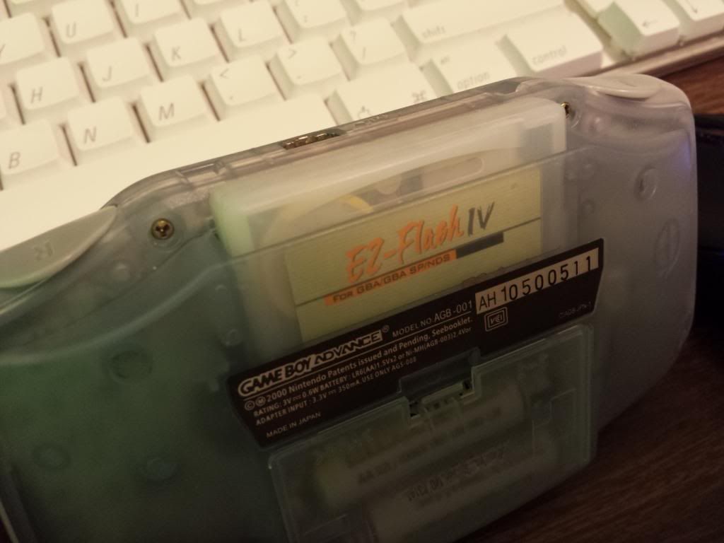
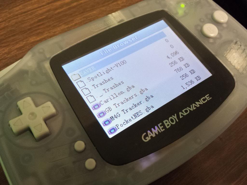
And of course it also begs for GBA sized dmg flash carts.
My flash cart
359 Mar 5, 2014 6:17 am
Re: Why no GBA Mods? (47 replies, posted in Nintendo Handhelds)
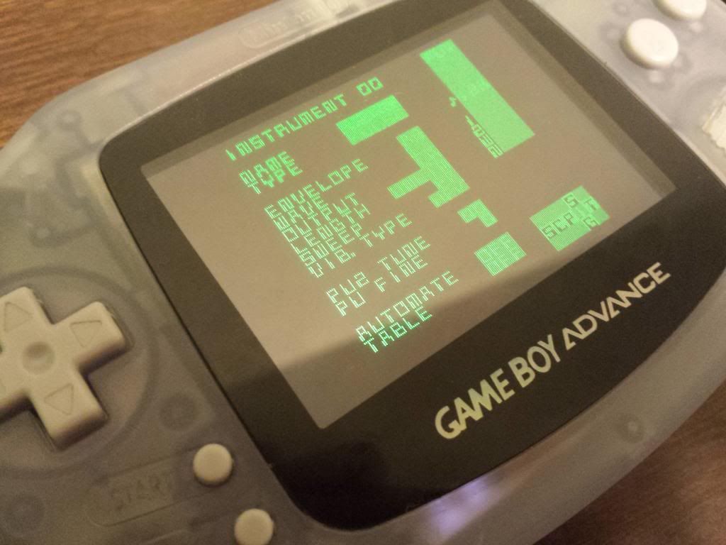
What are the benefits of using GBA for chiptune? I think DMG definitely has more space (an options) for mods. Is it better sound? Screen?
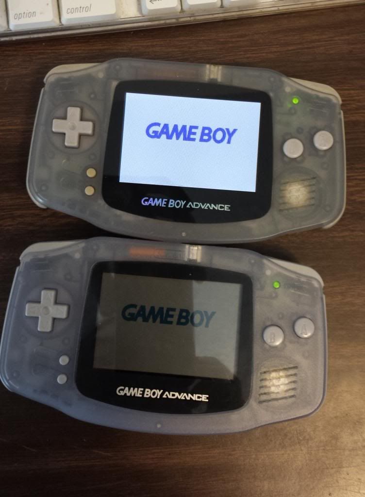
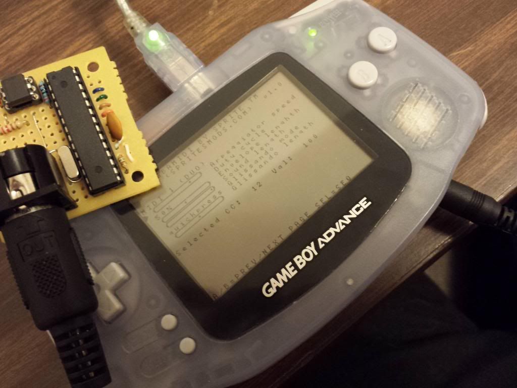
The screen is my main reason for loving the GBA. Also the Spritesmod GBAmidi cable is a large reason as well.
Seriously. GBA With Start Select on triggers, backlight and prosound?
Backlight, yes! Prosound is also possible, but I've yet to perform one.
360 Mar 5, 2014 6:04 am
Re: NSFMANIA 2A03 TOURNAMENT starting march the 5th! (that's tomorrow) (12 replies, posted in General Discussion)
The closest one would get to automatically converting it to NSF would be one of the Midi2MML programs. and even then alot would still have to be manually done. So the musician will inevitably have to learn one program or the other to input their notes into. But hey, I work manually by default. I write through a MidiNES and transcribe it into MML manually myself.
Some various limitations I have to suggest are the following:
No 11-bit noise. Only 7-bit
No triangle basses
'Song must be looped' would be an interesting one
Some type of filesize restriction would be fun. Like 1 bank only (8K)
No arps
A time signature restriction like no 4/4 and/or no 3/4
361 Mar 4, 2014 8:47 pm
Re: Sega Genesis Glitch Video Device (6 replies, posted in Sega)
Thats some seriously awesome gear, Matthew! Triggerboy looks cool too, though I'm not to big on using lsdj. I'm more of an NES and C64 guy. Does the audio trigger just divide the freq bands and turn those into separate 'on' signals based on their amplitude passing a threshold volume? cause That would be useful considering I got 3 relays I could use for bass mid and treb bands.
362 Mar 4, 2014 8:32 pm
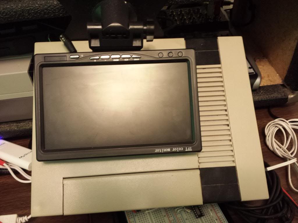
Re: D3th St4r Wild Builds & Nonsense (463 replies, posted in Nintendo Handhelds)
I would have gone with the TFT 7" monitor. Removing it from the stock enclosure would make it the perfect size IMO
363 Mar 4, 2014 6:02 pm
Re: NSFMANIA 2A03 TOURNAMENT starting march the 5th! (that's tomorrow) (12 replies, posted in General Discussion)
oops ![]() Thanks Sketchman
Thanks Sketchman
364 Mar 4, 2014 5:55 pm
Re: NSFMANIA 2A03 TOURNAMENT starting march the 5th! (that's tomorrow) (12 replies, posted in General Discussion)
Not to split hairs, but MIDI or not if the CPU itself can do it, the CPU can do it.
The CPU itself can't do it.
It is indeed a bummer, Sorry you can't participate. Maybe you can compose in your normal way and just transpose your song into a tracker or MML...
365 Mar 4, 2014 5:20 pm
Re: Sega Genesis Glitch Video Device (6 replies, posted in Sega)
Would love to see this thing hooked up w/ MIDI :DD
Me too!
I would buy you some arcade buttons to through in it of you promise you would do it.
I appreciate it, but I would have to make a whole new enclosure to fit larger buttons like that. Arcade buttons would feel awesome to play on though!
366 Mar 4, 2014 5:12 pm
Re: NSFMANIA 2A03 TOURNAMENT starting march the 5th! (that's tomorrow) (12 replies, posted in General Discussion)
well midi is a bit of a cheat, cause the 2A03 has certain timing limitations that something like MidiNES doesn't have. Like the whole 60 fps thing. Plus you can't submit a file that can be played in NSFplay if you only use midi. Also if one of the limitations ends up being a sample pack, you'd be 'down chip creek without a paddle'
367 Mar 4, 2014 4:52 am
Re: Best Genesis SVideo mod? (1 replies, posted in Sega)
I was getting some bad vertical lines on the simpler circuit. I went with the more complex one. Used 75Ω for chroma and 33Ω for luma.
Here's the David Howland version. 
And here's the Jamma-Nation-x version
I'm sure others might have gotten a better performance out of it than I did, but I was happy with the Howland circuit.
I noticed the link is dead. So, here is that circuit I used. Just remember to use 75Ω on the chroma output. using a 33Ω will cause bad bleeding. 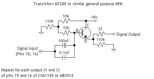
368 Mar 3, 2014 9:25 pm
Topic: Sega Genesis Glitch Video Device (6 replies, posted in Sega)
So, I've got something a bit special to share with you guys. Apart from it just being a nifty-cool device, I will be taking you though the build process, or should I say the 're-build' process. I've taken one of my old and early projects and 'remastered' it using techniques/skills I've learned long after I initially made the thing. So this is going to be a sort of before and after type showcase along with just showing off the device itself and the various stages within the re-build. I would also like to ask all of you if y'all have done anything similar with your old projects. Anyone have any similar experiences with reworking an old project using your current and more proficient modding prowess? I'd seriously love to hear your stories about it.
Now without any further blabbing by me, let's get to our feature presentation ![]()
First lets take a look at my original machine. Sorry but I only really have this one photo of it as I didn't expect I was going to be documenting the build process as much as I ended up doing.

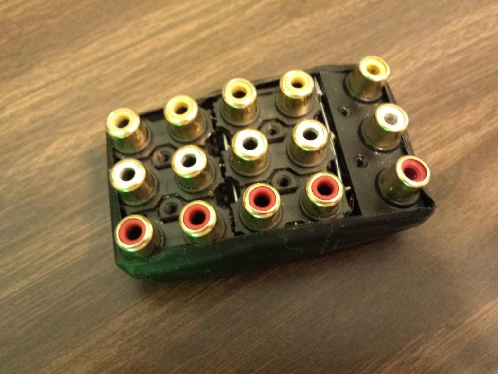
Notice the tape and loose wires? The wires are soldered directly to the bend points and coming right out of a hole in the back. The RCA assembly is merely taped to the genesis. Sure, It looks a bit cool and grungy, but I'm the type of person in which the pride I have for my work is directly proportional to how professional I can make it look.
I was rather inexperienced and had no income, so I used whatever I had available to me. I used components found from inside various devices around my garage and closet. My first instinct was to just do switches like some interesting Speak&Spell bends I had seen at the time, but luckily I had enough foresight back then to know that switches would be incredibly limiting compared to the more modular approach using these RCA connections.
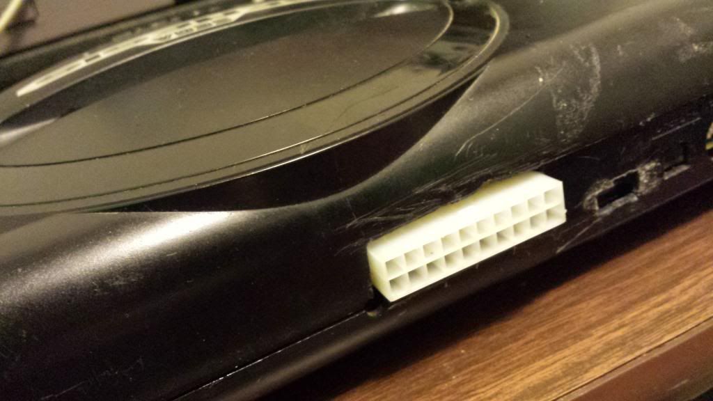
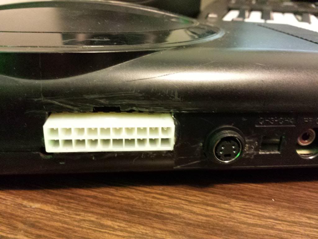
Now the first step I created for myself was to make this thing removable so the Genesis could revert back to it's clean original state. I eventually decided on using a 20 pin molex connection. These are found on nearly every single computer power supply, so I had both male and female connectors already available to me on a dead computer. I just harvested the header from the motherboard and cut the mating connector from the supply. It conveniently already had wires attached so that was clearly the best choice for me.

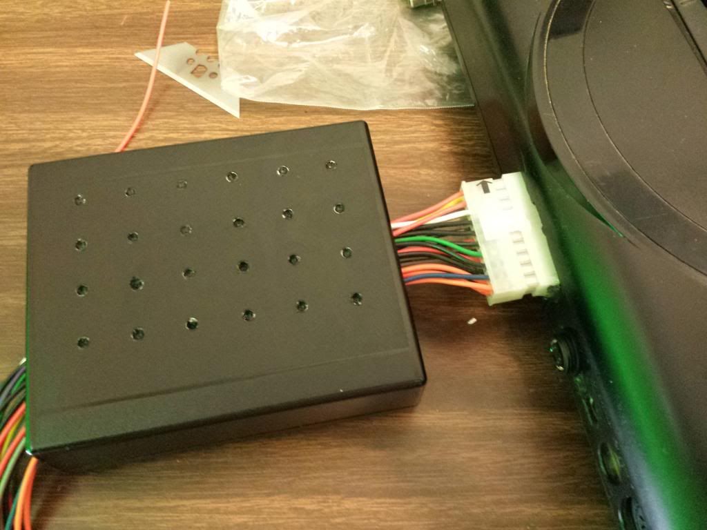
This becoming a removable mod required me to acquire a suitable enclosure for everything. So I did some searching around on Mouser and DigiKey 'till I found a lovely little box close the exact dimensions I needed.
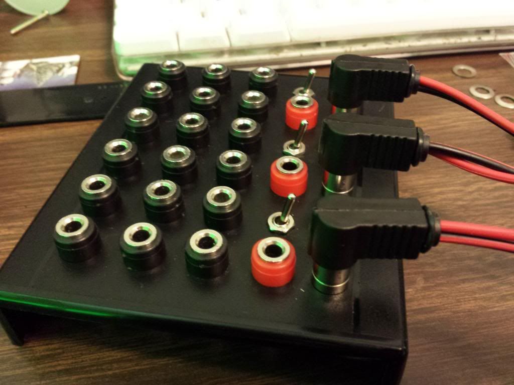
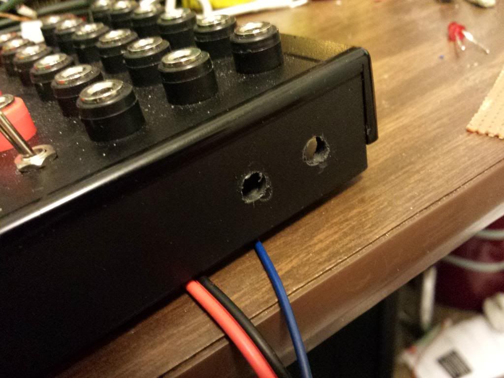
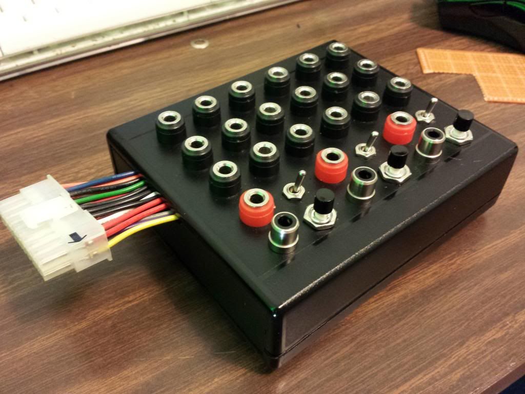
Next I decided that banana plugs were a much better choice than the RCA jacks in my original version. So after those critical pieces were decided on, I could start designing my panel layout. Placing the components derctly on the encloser and taping the sides helped me to more accurately measure where all my holes should go.


Once I was happy with my configuration and marked the exact location of each hole, I started drilling and placing my parts. In my case I used a dremel to actually make the holes because I could slowly round out each hole in any direction I wanted in case they were a bit skewed or uneven. Power drilling, to me, is just way too quick and final. Once I drill out a hole, it's over in seconds and I'm stuck with whatever unevenness I may have done on accident. The dremel allows me to have a bit more control.

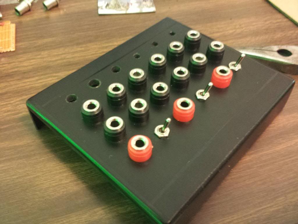
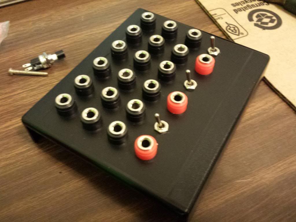
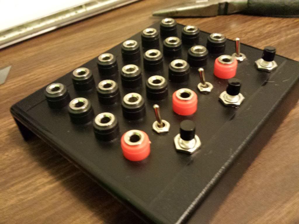

Now that we can see this thing coming together a bit, I can finally start going over the functionality with you. As you have probably guessed the black plugs are the original bend point found in my RCA version. The rest of the switches and plugs might not be quite as obvious to some. So this next piece to the puzzle will make things a lot clearer to those of you still wondering. It plays a very important role in my design.
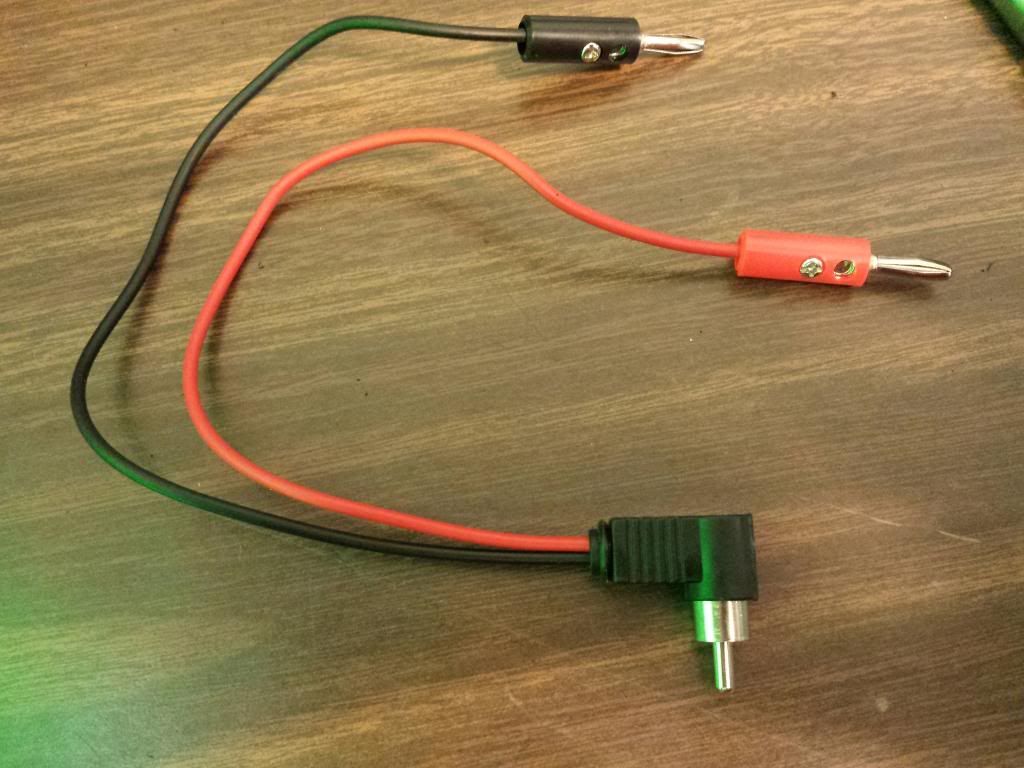
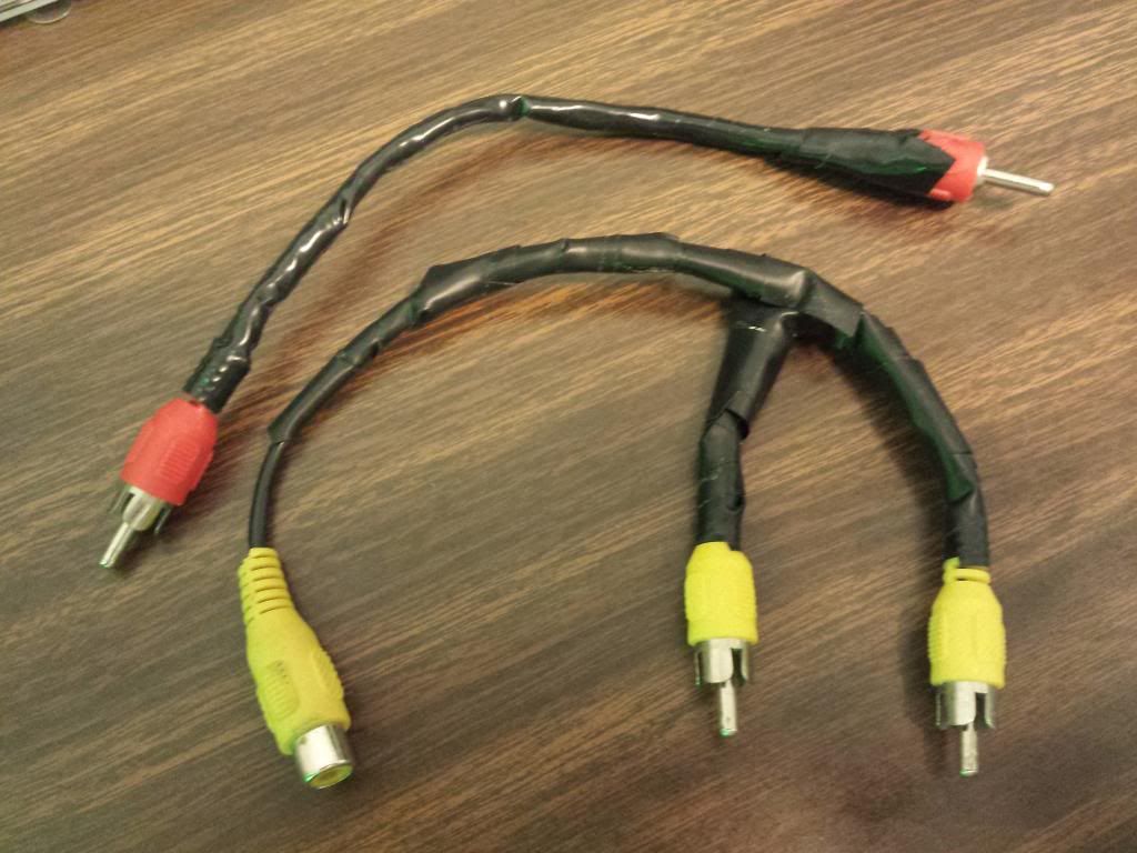
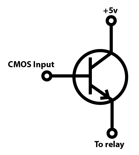
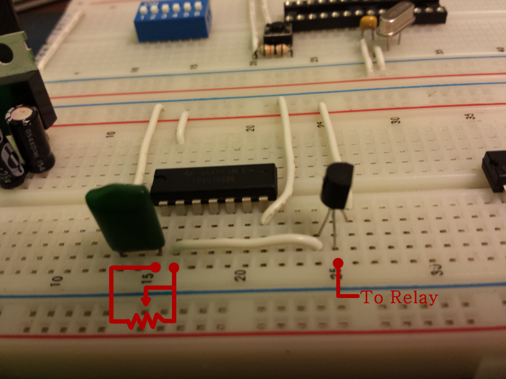
The wire! I created this cable myself for the sole porposes of this project. The RCA connects into my pannel and the banana leads go to any of the black bend points. The actual connection can be initiated in one of three ways. By a momentary pushbutton for VJing in time to music, with a simple switch for making a hands free constant connection, or via the red jacks which are connected directly to the coil pins of 3 relays. So I can feed in the pulses from a simple 40106 clock, a CMOS binary counter, or even use something like an AVR Microcontroller to trigger the relays. One thing to note here is that a raw logic signal from these cmos devices will not be enough to engage the relays. I will have to connect my pulse signal to the base of an NPN transistor and use the collector and emitter to feed a 5v signal to the relay.
› Relay Driver
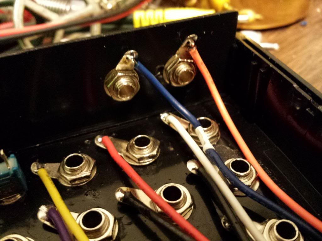
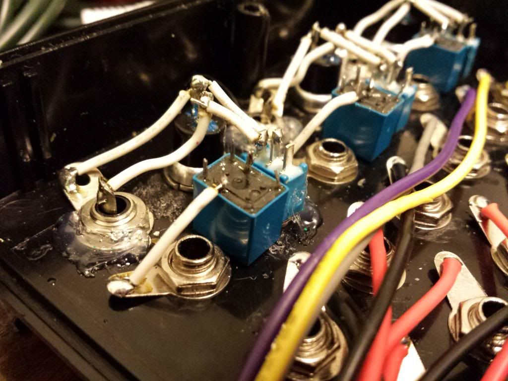
Now that I have the layout done and complete. It is time to wire this baby up! Lets take a look and the under side.
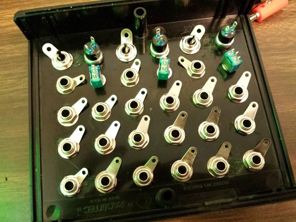
Now to me that looks very neat and clean. LETS KEEP IT THAT WAY. To make that happen I use solid core wire because it will keep its shape fairly well and it's easier to strip with minimal mess. Now in order to keep things as neat and tidy as possible, I only cut my wires to the minimum length required to make the connection.
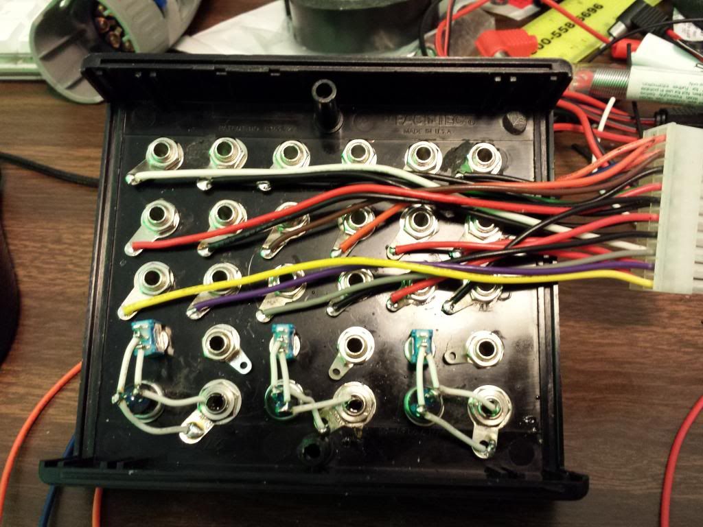
Now if you look down the length of these wires you might notice a bit of spiraling going on.
You may be thinking 'Hey Tyler, that doesn't look as neat as it could with the wire laying a bit more flat. What gives?' Now I would agree with you, but the reason for this is because I wanted the order of the jacks to directly match the order of the molex pinout. So jack one on my panel is pin one on my molex. Organisation is more important to me than evenly laying wires. Besides, I still find this implementation very tidy.
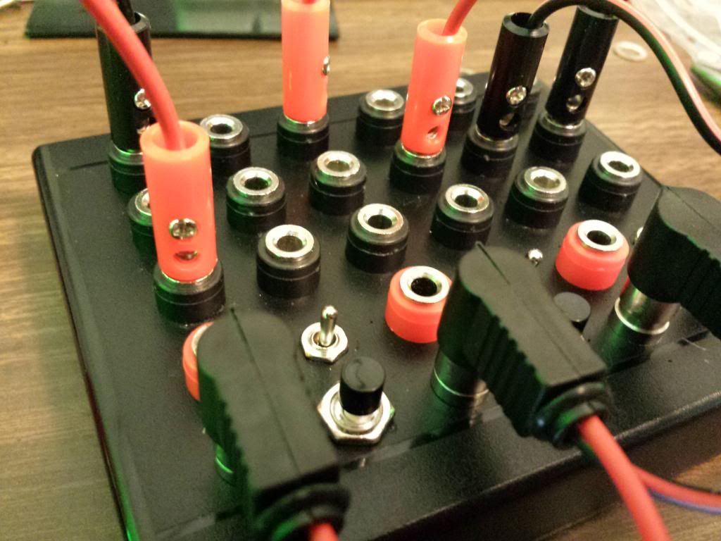
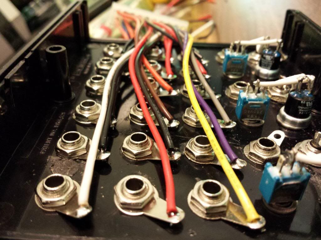
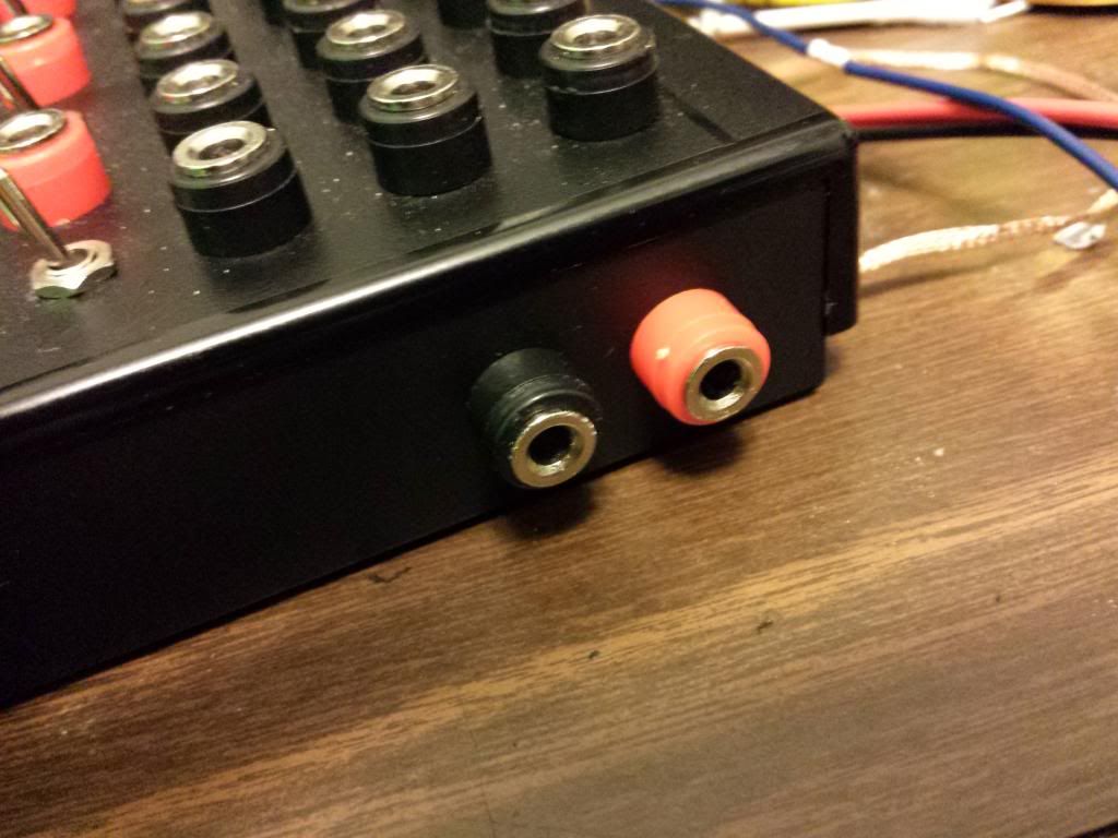
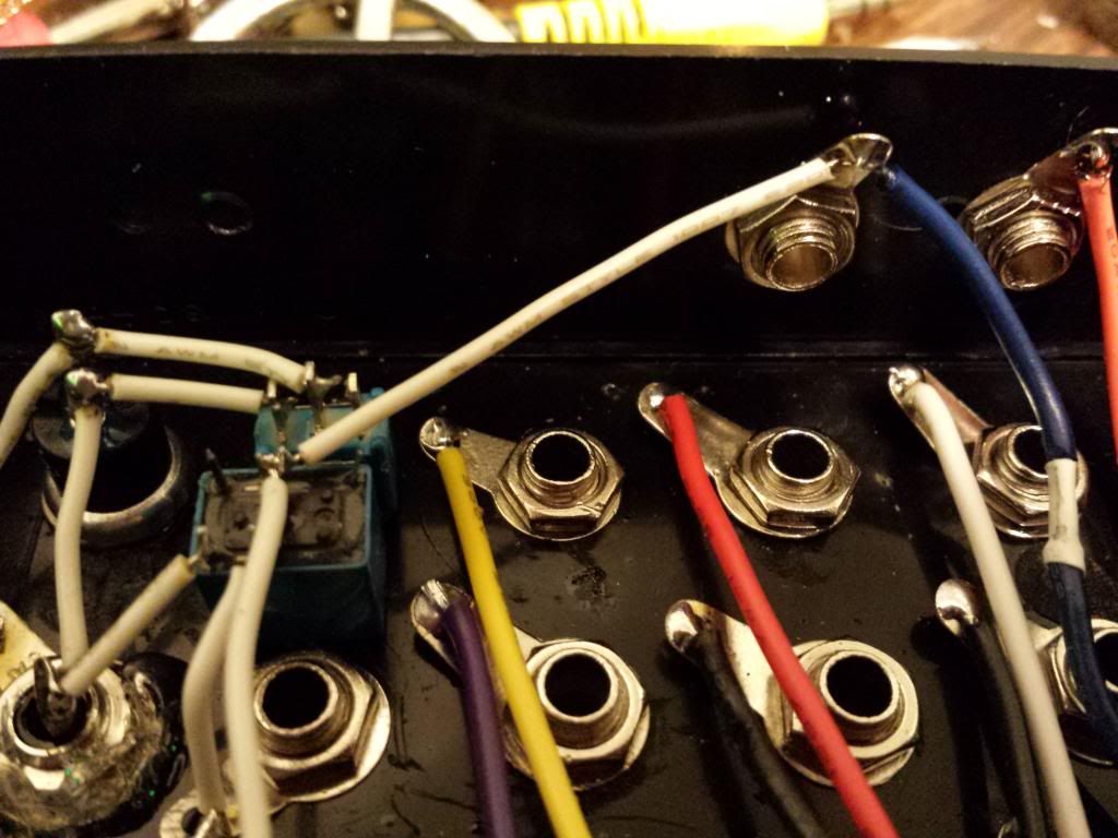
Now I have left two wires coming from my molex unconnected at this stage. These are going to be connected to two jacks that we'll put on the side, giving us access to the +5v, and more importantly, the GND coming out of the Sega. Orange is positive and Blue is ground.
› Quick tip:
I then installed the two banana jacks on the side that will give me access to the Sega's power. The Ground is particularly important because we will need to connect it to the ground of any outside circuit we plan on using the signals from to control the relays. I included the 5v jack incase I want to power these external devices straight from the sega. I really don't like using batteries. Whenever it is possible, I avoid using them. I don't like any consumables that will need replacing down the line. Plus, if it's just a couple cmos chips or a simple micro, the current drawn will not cause any problems to the Genesis.
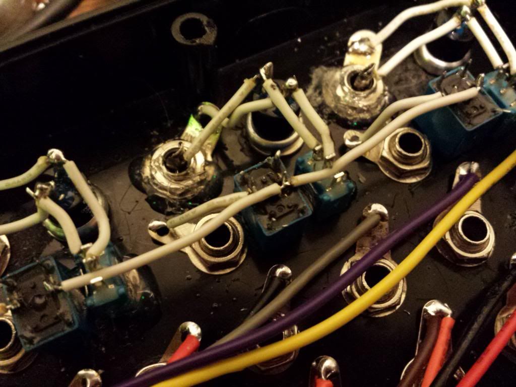
So for the relays, I used OEG OUC-SH-105D relays. they were the smallest I could find for cheap. 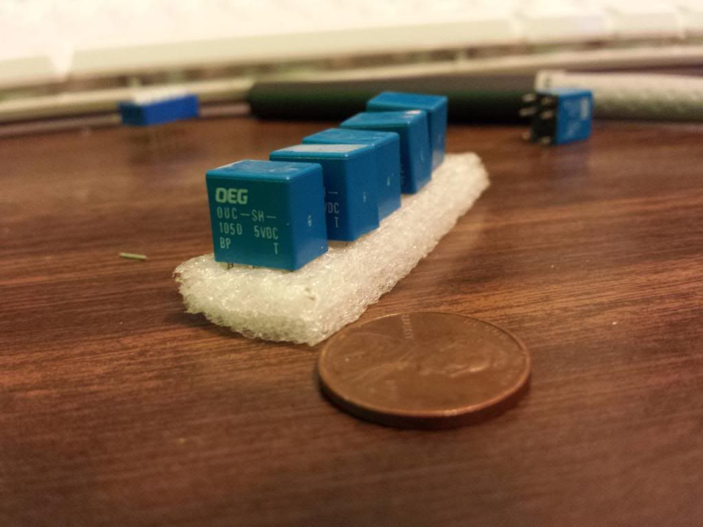
To keep the relays stable, I've hot glued the relays in place next to the toggle switches and begin wiring just as before. You'll notice I also hot glued some other parts down that needed a bit of extra help staying tight and snug on the enclosure.
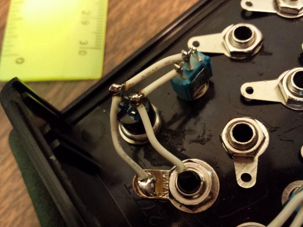
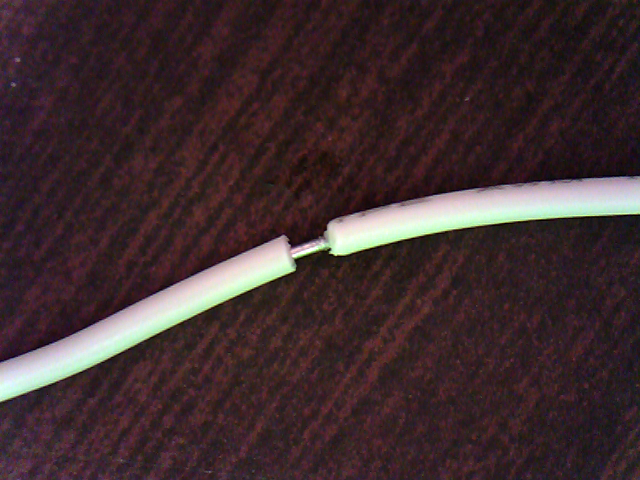
Now there was one wire I did something a bit neat to. For the wire I used to connect all the relay's ground pins, instead of using two wires and soldering both to the middle relay, I stripped the insulation half way down the wire so I could just solder one wire to 3 points. I didn't think of it till quite late in the build, so I wish I had done that on several other connections. It even kind of illustrates what I mean when I refer to the modding skills I have learned over time that initially sparked this re-build. You never know when a new technique will find it's way to you.
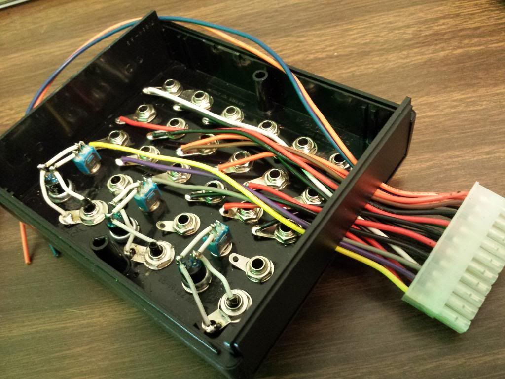
Now I finish up the relay wiring and connect them to my ground jack on the side.

After the relays have been successfully installed, the box is completed. I'm not sure about you, but I very much prefer this over the old messy RCAs. ![]()
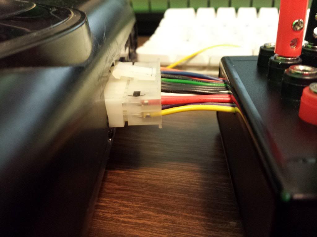
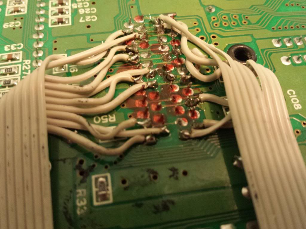
As for the stuff on the Genesis side of things, there actually isn't much to it. Just a ribbon cable from bend points to the molex connector. Thats it. (The orange marks on the solder points are markers for the bends I didn't really care for when I was experimenting)


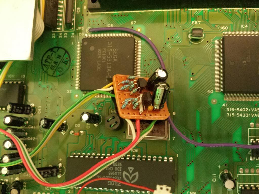
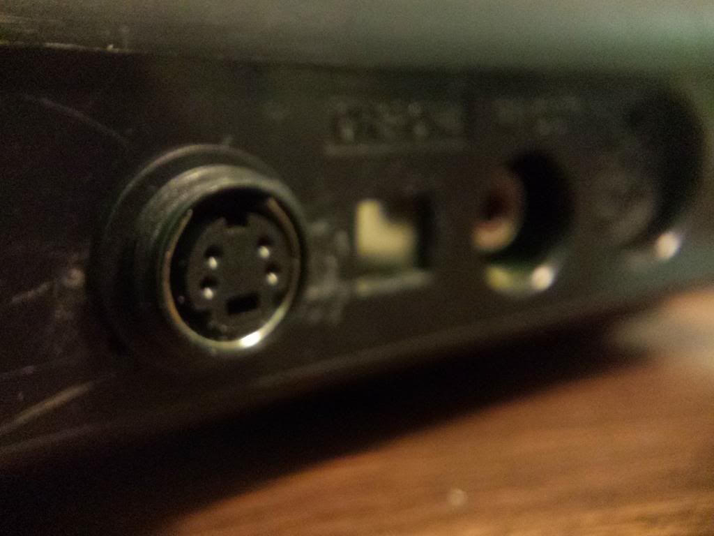
Also, considering this mod is all about the video signal of the Genesis, I obviously wanted to throw in an S-Video mod. No point in glitchin the system if I can't record the video in the best quality possible right?
Heres the schematic I used. The chroma has a 75Ω resistor on the signal output and the Luma uses a 33Ω. 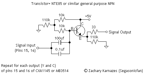
(The rca's pictured on the right were going to be for an alternate audio connection but I decided against it.)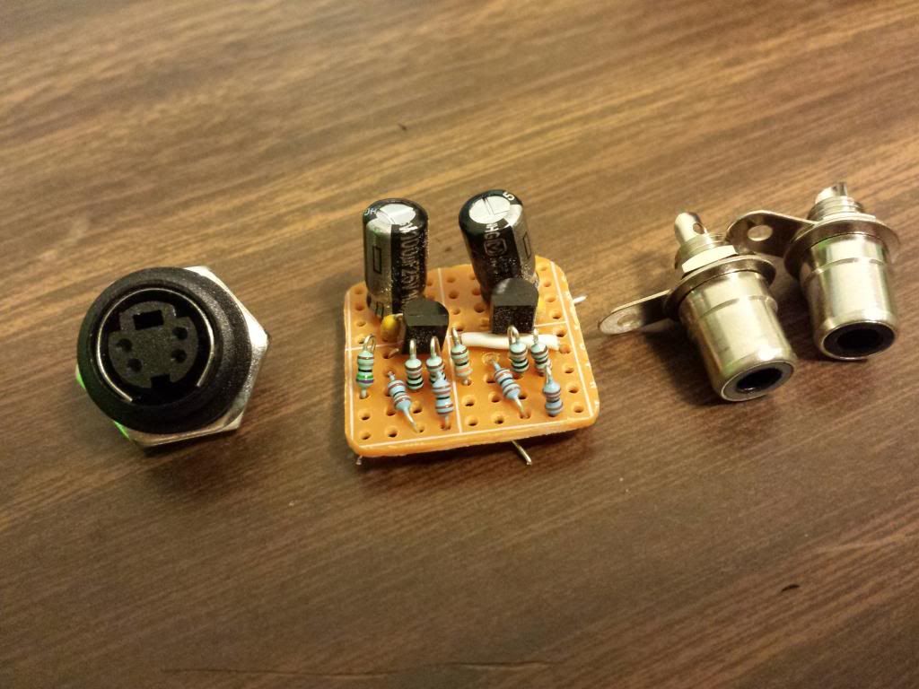
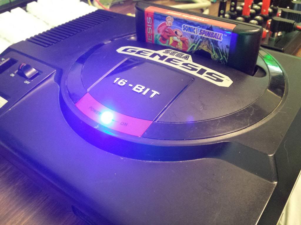
Naturally, I also had to throw in a mega bright blue LED!
And now finally, lets see this thing in action!
And that, my friends, completes this adventure. I hope you had fun and I hope you learned a few things. I had a great time working on this project again, and it really feels good when something comes full circle and turns out just as expected. Thank you for joining me on the journey!
P.S. If anyone knows of any projects out there that will let me MIDI control the relays, give me a shout! Something that easy to build with little parts would be excellent.