1.Install Ableton
2.Make dubs that be steppin
3.Sprinkle in some chips
4.Profit?
97 Sep 28, 2012 3:33 pm
Re: Need a "chip step" tut, can some one redirect me? (40 replies, posted in Tutorials, Mods & How-To's)
98 Sep 24, 2012 12:46 am
Re: Internal ArduinoBoy Kit Preorder - Uncommon Electronics (108 replies, posted in Trading Post)
I'm very interested in a front PCB perhaps a few buttons as well.
99 Sep 12, 2012 8:34 pm
Re: Pizza Trade El Numero Dos (II) (33 replies, posted in Trading Post)
What is the email you'd like us to send it to?
100 Sep 3, 2012 5:52 pm
Re: Awesome Force - The Morning After (3 replies, posted in Releases)
Awesome!
101 Aug 30, 2012 2:48 am
Re: looking to buy a crystal oscillator (6 replies, posted in Trading Post)
http://www.getlofi.com/?page_id=1302
http://www.thursdaycustoms.com/product/ … e-clock-v1
http://www.thursdaycustoms.com/product/ … e-clock-v2
I assume this is more of the thing your in the market for.
Variable oscillators are neat o
102 Aug 28, 2012 8:04 pm
Re: Losing the right channel when closing (switched both pcb's) (14 replies, posted in Nintendo Handhelds)
103 Aug 28, 2012 7:28 pm
Re: A Pixel Art Drop Box (1,052 replies, posted in Graphics, Artwork & Design)
please try to post just pixelart. I know this is related but it's not actually pixelart
btw, check this
http://www.flickr.com/groups/gameboycamera/
Whoops, my bad.
104 Aug 28, 2012 7:12 pm
Re: Losing the right channel when closing (switched both pcb's) (14 replies, posted in Nintendo Handhelds)
You could try replacing the wheel potentiometer for the volume control. I tried it and it worked for myself so I don't know give it a shot.
105 Aug 19, 2012 6:52 am
Re: A Pixel Art Drop Box (1,052 replies, posted in Graphics, Artwork & Design)
106 Aug 16, 2012 2:12 am
Re: Semi-Custom LSDj Keyboards: Research Thread (39 replies, posted in Trading Post)
That paint job looks Rad! Excellent work, like the matching color scheme with the dmg.
Like the PS2 socket placement as well kudos.
107 Aug 15, 2012 8:51 pm
Re: Game Boy Pocket LCD Issue (21 replies, posted in Nintendo Handhelds)
Firstly I'd like to take into account that I have absolutely no experience or knowledge of the 'Gameboy Pocket'. Despite that I'd assume their fairly similar, so hopefully there will be something of use to you in this post.
I've encountered an identical problem twice very recently with my DMGs.
Here was the situation I was in
DMG1: The ribbon cable &/or the female cable connecter solder points were at fault
DMG2: The ribbon cable is very touchy and glitches until held in a very certain position
DMG3: Still kicking
I'll start with DMG2 as it was the easier of fixes. The pins on the ribbon cable had small scratches from where the metal had been etched away where they make contact with the innards of the port. Ergo, the lack of available metallic surface became to significant for certain pin/s to function properly. My first thought was to solder the recesses in the ribbon cable pins. This procedure kinda sucks, too much solder on the any one of the pins can easily result in the cable being to thick...
At this point in time, an ingenious thought had presented itself too me. The ribbon cable's pins are excessively longer then needed. I simply cut the pins right along where the etches began making sure to cut evenly so the cable wouldn't fit in sloppy or crooked. After reinserting the cut cable back into the port the screen worked like new again.
Now for DMG1, I went a little overboard with the soldering iron that day. ![]()


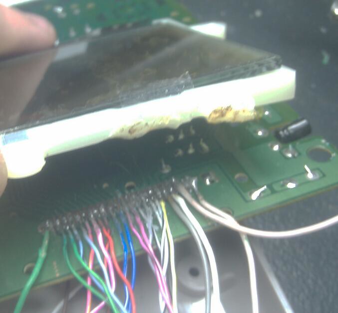
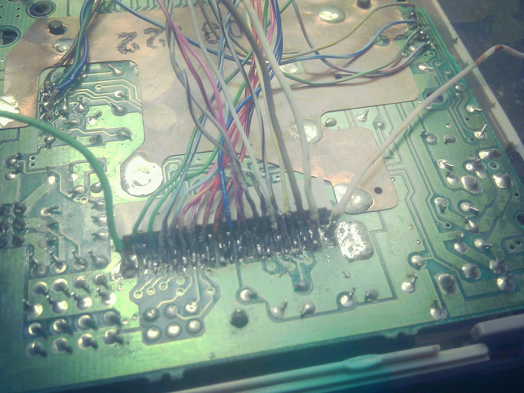
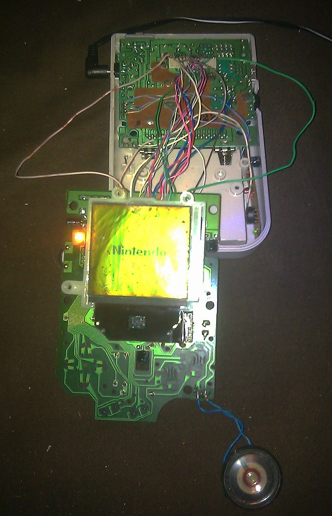
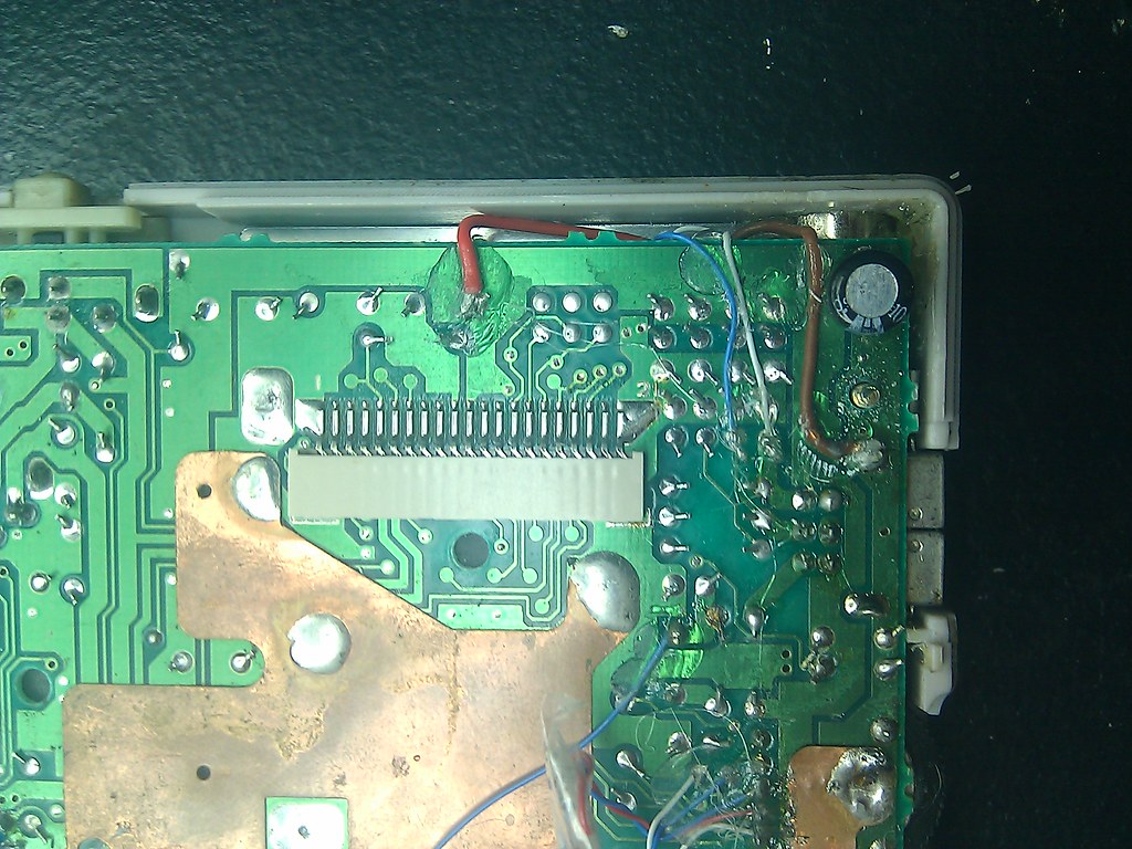
Same issues as DMG2, except the cable port wasn't sending any screen data at all not even a glitch, and the ribbon cable had even more problems. So with nothing better to do and a lot of time and patience on my hands I went to the next logical step to solve both issues by the mess of wires you see above. After completing all that wiring and verifying my solder work, too my surprise the thing actually came back to life.
I wouldn't recommend doing the latter of the two repairs.
Sadly though after that whole entire process, I look through my drawer and find a perfectly intact DMG ribbon cable I had salvaged a while back. I replaced the wire mess for the new found cable but was ultimately shut down as I seem to fuck up either of the vertical/horizontal cable that connect the screen to its PCB.
[Note: The plastic housing for the screen was melted ended up replacing after the picture also the display worked fine in the last picture. I didn't have an extra backlight so what your looking at is the torn off reflective and polarization layer that I placed back behind the glass.]
108 Aug 11, 2012 2:09 am
Topic: Gameboy EXT ---> 25 pin parallel (4 replies, posted in Nintendo Handhelds)
I am on a mission to get these damn gameboy camera photos off of the sram and onto my hard drive. Mind you, I don't own a MegaMemoryCard, Cart reader, or Mad Catz camera cable or this process would be so much simpler.
So my only viable option to build my own cable based off whatever schematics on numerous outdated foreign websites. I do have male 25 pin serial port adapter, a spliced DMG EXT cord, several 2N3906 transistors, and a dedicated 98 machine running to test this out on.
Schematic:![]()
Site that has some good info: http://emuconsoleexploitnews.blogspot.c … -post.html
Site that has actual picture of wiring: http://translate.googleusercontent.com/ … #eric_pict
I'm a bit confused as to the wiring process when the transistors gets involved. (Also do I need a diode?)
The transistor has 3 pins.
Pin1: Emitter
Pin2: Base
Pin3: Collector
These pin definitions mean absolutely nothing to me.
As for the software I've been using gbcam2.
Has anyone had any experience building one of these cords?
109 Aug 10, 2012 8:15 pm
Re: DMG Speaker Replacement (13 replies, posted in Nintendo Handhelds)
I have several extra speakers PM if needed
110 Aug 3, 2012 12:35 pm
Re: Semi-Custom LSDj Keyboards: Research Thread (39 replies, posted in Trading Post)
So, I decided to contact Justin again, this time as to the wiring method he chose to use.
Both diagrams work, although the first of the two is just more convenient to solder.
The wiring looked perfectly normal. He then suggested I break out a multi meter.
None of the wires responded the way they should have to a multi meter.
This was the turning point in the whole keyboard escapade.
Shortly after I disassembled the PS/2 socket (removing all that hot glue was a bitch). I discovered that thin data wire had been separated from the socket. Replaced wires with something a little more sturdy. I then just reassembled and remounted the port.
Suddenly plug in keyboard...
hit a button...
whats this?
a note of E6.![]()
![]()
![]()
![]()
![]()
Fuck yeah, months and months of trial and error leading up too this one note.
I can now attest the 'OG KBJ-006B' really is an excellent candidate for use as a dedicated LSDJ keyboard sync device.
Nada worries my good man, I would feel comfortable selling this exact keyboard. It's anything but a bunk/not fully tested/unverified keyboard at this point in time. This keyboard is about as good as it gets for functionality and overall awesomeness. I'd recommend this device to any member of the chip community having trouble at their local thrift store. The 'OG KBJ-006B' is worth every penny IMHO, especially if it came with a wicked paint job ![]()
Telerophon, the LSDJ PS/2 keyboard sync woes are over!!! I can not thank you enough for your involvement in this project. I simply couldn't have done it alone.
111 Aug 1, 2012 1:15 am
Re: Case Lighting n such (6 replies, posted in Tutorials, Mods & How-To's)
Your saying, if I were to buy a few SMT LEDs from your site; There would be no need for any resistor calculation or purchasing?
So I'd just wire them straight to the +5v?
112 Aug 1, 2012 12:56 am
Re: Case Lighting n such (6 replies, posted in Tutorials, Mods & How-To's)
Understandable. To make my intentions a little clearer if I were to buy a few of these LEDs: http://www.nonelectronics.com/catalog/i … 61fc775020
What resistors would I need? As for wiring, can the LEDs be wired in a series from a single +5v or must they each be wired individually needing their own resistors?


