17

(28 replies, posted in Nintendo Handhelds)

Jazzmarazz wrote:

That is strange. I probably won't need to fuss with data_Latch until I get a steady image but I appreciate the input. Do you know if the pixel data remains at its value between that "short delay" or does it return to blank (00)? I assume I will find a stripe down the left side of the screen once I get a steady image?

Apparently it is to do with the shift register for the LCD only having 159 stages - you'll find more detail at the bottom of this page:

http://blog.kevtris.org/blogfiles/Nitty … Timing.txt

I can't speak to the state of the GameBoy's DATA lines during DATA_LATCH as I've only looked at this from the perspective of controlling the lines independently of the GameBoy CPU for my Arduboy Classic project.

18

(28 replies, posted in Nintendo Handhelds)

Jazzmarazz wrote:

AWESOME WORK! big_smile

A couple of points that may or may not help:

HSYNC is on pin 18 (occurs at the same time as VSYNC). Pin 17 is DATA_LATCH (does not occur at the same time as VSYNC).

The first pixel for each row is clocked out while DATA_LATCH is high, and then there is a short delay before the remaining 159 pixels in that row are clocked out.

19

(19 replies, posted in Nintendo Handhelds)

catskull wrote:

Wow, great work!

Thanks!

Another idea would be to simply solder the arduino into the board without the headers, I'm sure you've thought of that though.

Yep, the problem then is that the USB ports are too low to be accessed through the opening for the cartridge slot in the case - need to find a good middle ground! smile

Do you have more details of the actual functionality of this board? Why are two arduinos needed? How is it powered during operation?

Basically, the Arduino Micro is running modified Arduboy sketches, and the Arduino Nano is acting as an LCD controller for the GameBoy display. At the moment, the Arduinos are powered through their USB ports.

I go into a lot more detail in the thread on the Arduboy community:

http://community.arduboy.com/t/arduboy-classic/293

How hard would it be to power the unit off the 4 AA's the gameboy uses? And while you're at it, why not include an on/off switch where the original one went?

Wouldn't be hard at all, and I have found a supplier for a switch that fits. At this stage I am just happy to have a board with all of the connections fixed in place, and be able to move away from the breadboard and the worry of the rats nest of wires I was using coming loose!

Eventually, all of the components from the two Arduinos could be migrated over and everything included on the one board - just means more work and time and money! wink

20

(19 replies, posted in Nintendo Handhelds)

And here it is! big_smile


The one hitch is that the Nano is only just marginally too tall for the case, so I'll need to source slightly shorter female headers... or just make a little cut-out in the case!

21

(19 replies, posted in Nintendo Handhelds)

catskull wrote:

Looks great man! You didn't need my help after all. Is that ribbon connector supposed to be off center like that?

Ha! Thanks - I still appreciate the effort, and was definitely a motivator to have someone showing interest!

Yes, Nintendo made the ribbon cable a little off center for some reason?

catskull wrote:

Do you have plans for a ground fill?

There are connections all over the place so not sure I'd have space available on one of the layers for a ground fill? Am planning to at least make the ground and power lines a little thicker though...

22

(19 replies, posted in Nintendo Handhelds)

Have had a couple of offers of help, I had some time on my hands today so I managed to muddle through and put some work in and come up with what I think is pretty close to a first prototype attempt at least!

23

(19 replies, posted in Nintendo Handhelds)

So... there is room for the two Arduinos (with ICSP headers removed) to sit with their legs up 'dead-bug' style in the GameBoy's cartridge cavity, with their USB ports accessible through the cartridge slot:


I am still learning the ropes in Eagle, but have managed to get as far as creating a couple of the custom parts needed, making all of the electrical connections, and a basic layout of where things should fit:

Now, I know there are a few Eagle 'gurus' here in the forum, and this is where I was hoping someone might be able to help out with the last push of routing signals and getting the PCB to match with the size and the mounting holes of the original GameBoy motherboard, as well as making sure all of the components are positioned correctly so that they avoid colliding with any of the mounting posts and plastic walls inside the shell. And getting the volume dial and ribbon cable connector to line up with their original positions!

Help? smile

24

(19 replies, posted in Nintendo Handhelds)

Thanks!! big_smile

What would be really cool, would be to play with this setup attached to one of kitsch's long-awaited  'all-new' LCD PCBs!

25

(19 replies, posted in Nintendo Handhelds)

Introducing, a prototype of what I am tentatively calling the Arduboy 'Classic'. Using an Arduino Leonardo (same ATmega32U4 microcontroller as the Arduboy), but with the screen, the buttons, the speaker, and the LED indicator all being provided by the front half of a classic Nintendo GameBoy!

Full details on the Arduboy forum: http://community.arduboy.com/t/arduboy-classic/293

Here's a video of the prototype running some adapted Arduboy demos:

Never mind...

27

(6 replies, posted in General Discussion)

Yeah, that was 'Commodore USA':

http://en.wikipedia.org/wiki/Commodore_USA

Looks like they might be bringing them back under a different company name:

http://www.myretrocomputer.com/home.html

I have plenty of AVR experience and would be happy to have a crack at it - but what exactly could be gained by messing with just the MIDI implementation and not the NES code?

29

(3 replies, posted in General Discussion)

Apeshit has one:

http://chipmusic.org/forums/post/168786/#p168786

30

(20 replies, posted in Nintendo Handhelds)

NES compatibility! smile

31

(20 replies, posted in Nintendo Handhelds)

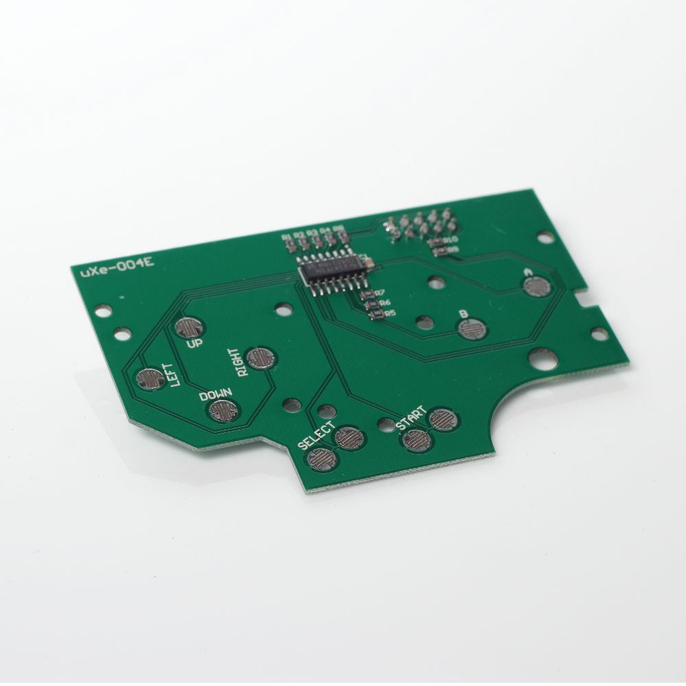
That's a 4021 shift register onboard - it's basically a NES controller PCB in the shape of a DMG button PCB... Which means only 5 wires instead of 9!

32

(20 replies, posted in Nintendo Handhelds)

Vile wrote:

This would be even easier with kitchs' common ground dmg button pcb I'd imagine!

...the 3D model is designed for a hacked up SNES controller though, not sure it will line up exactly with the actual DMG layout without some modification to the 3D model?

I was thinking of reworking my uXe-004E PCB design to fit with this PiGRRL concept, maybe including an accelerometer onboard if there is interest?