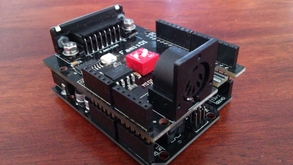
Here's the updated code - a toggle switch connected to pin 12 will select between MIDI or Joypad mode:
EDIT: updated again...
#include <MIDI.h>
int unmappedBend;
byte mappedBend;
static byte bitMask[] = {1, 2, 4, 8, 16, 32, 64, 128};
void setup()
{
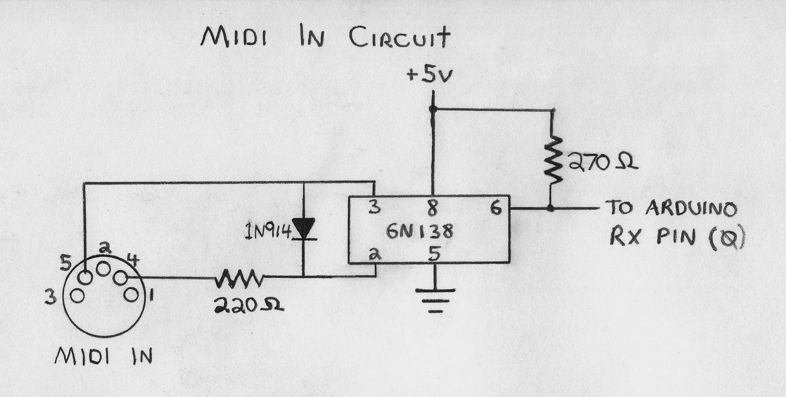
pinMode(0, INPUT); // MIDI IN
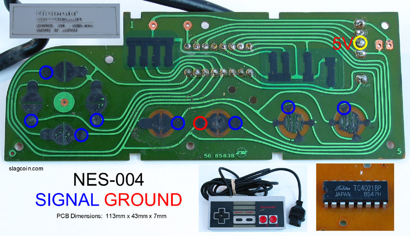
pinMode(11, OUTPUT); // 4021 D7 (A Button)
pinMode(10, OUTPUT); // 4021 D6 (B Button)
pinMode(9, OUTPUT); // 4021 D5 (Select)
pinMode(8, OUTPUT); // 4021 D4 (Start)
pinMode(A3, OUTPUT); // 4021 D3 (Up)
pinMode(A2, OUTPUT); // 4021 D2 (Down)
pinMode(A1, OUTPUT); // 4021 D1 (Left)
pinMode(A0, OUTPUT); // 4021 D0 (Right)
pinMode(A5, INPUT); // A Button
pinMode(A4, INPUT); // B Button
pinMode(2, INPUT); // Select
pinMode(3, INPUT); // Start
pinMode(4, INPUT); // Up
pinMode(5, INPUT); // Down
pinMode(6, INPUT); // Left
pinMode(7, INPUT); // Right
pinMode(12, INPUT); // Toggle Switch
// set OUTPUT pins HIGH
PORTB |= B00001111; // pins 8, 9, 10 and 11
PORTC |= B00001111; // pins A0, A1, A2 and A3
MIDI.begin(MIDI_CHANNEL_OMNI);
}
void loop()
{
if (PINB & bitMask[4])
{
if (MIDI.read() && (MIDI.getType() < B11110000))
{
if (MIDI.getType() == NoteOn && MIDI.getData2() > 0)
{
if (MIDI.getData1() == 60) // C4
PORTB &= ~bitMask[3]; // A
else if (MIDI.getData1() == 62) // D4
PORTB &= ~bitMask[2]; // B
else if (MIDI.getData1() == 64) // E4
PORTB &= ~bitMask[1]; // Select
else if (MIDI.getData1() == 65) // F4
PORTB &= ~bitMask[0]; // Start
else if (MIDI.getData1() == 67) // G4
PORTC &= ~bitMask[3]; // Up
else if (MIDI.getData1() == 69) // A4
PORTC &= ~bitMask[2]; // Down
else if (MIDI.getData1() == 71) // B4
PORTC &= ~bitMask[1]; // Left
else if (MIDI.getData1() == 72) // C5
PORTC &= ~bitMask[0]; // Right
}
else if (MIDI.getType() == NoteOff || (MIDI.getType() == NoteOn && MIDI.getData2() == 0))
{
if (MIDI.getData1() == 60) // C4
PORTB |= bitMask[3]; // A
else if (MIDI.getData1() == 62) // D4
PORTB |= bitMask[2]; // B
else if (MIDI.getData1() == 64) // E4
PORTB |= bitMask[1]; // Select
else if (MIDI.getData1() == 65) // F4
PORTB |= bitMask[0]; // Start
else if (MIDI.getData1() == 67) // G4
PORTC |= bitMask[3]; // Up
else if (MIDI.getData1() == 69) // A4
PORTC |= bitMask[2]; // Down
else if (MIDI.getData1() == 71) // B4
PORTC |= bitMask[1]; // Left
else if (MIDI.getData1() == 72) // C5
PORTC |= bitMask[0]; // Right
}
else if (MIDI.getType() == PitchBend)
{
unmappedBend = (int)((MIDI.getData1() & B01111111) | ((MIDI.getData2() & B01111111) << 7));
mappedBend = map(unmappedBend, 0, 16383, 165, 5); // Arkanoid Paddle range, centered at 170 (+/-80)
// Paddle Position
if (mappedBend & bitMask[7]) // A
PORTB &= ~bitMask[3];
else
PORTB |= bitMask[3];
if (mappedBend & bitMask[6]) // B
PORTB &= ~bitMask[2];
else
PORTB |= bitMask[2];
if (mappedBend & bitMask[5]) // Select
PORTB &= ~bitMask[1];
else
PORTB |= bitMask[1];
if (mappedBend & bitMask[4]) // Start
PORTB &= ~bitMask[0];
else
PORTB |= bitMask[0];
if (mappedBend & bitMask[3]) // Up
PORTC &= ~bitMask[3];
else
PORTC |= bitMask[3];
if (mappedBend & bitMask[2]) // Down
PORTC &= ~bitMask[2];
else
PORTC |= bitMask[2];
if (mappedBend & bitMask[1]) // Left
PORTC &= ~bitMask[1];
else
PORTC |= bitMask[1];
if (mappedBend & bitMask[0]) // Right
PORTC &= ~bitMask[0];
else
PORTC |= bitMask[0];
}
}
}
else
{
delay(1);
// read Joypad buttons directly
if (PINC & bitMask[5]) // A
PORTB |= bitMask[3];
else
PORTB &= ~bitMask[3];
if (PINC & bitMask[4]) // B
PORTB |= bitMask[2];
else
PORTB &= ~bitMask[2];
if (PIND & bitMask[2]) // Select
PORTB |= bitMask[1];
else
PORTB &= ~bitMask[1];
if (PIND & bitMask[3]) // Start
PORTB |= bitMask[0];
else
PORTB &= ~bitMask[0];
if (PIND & bitMask[4]) // Up
PORTC |= bitMask[3];
else
PORTC &= ~bitMask[3];
if (PIND & bitMask[5]) // Down
PORTC |= bitMask[2];
else
PORTC &= ~bitMask[2];
if (PIND & bitMask[6]) // Left
PORTC |= bitMask[1];
else
PORTC &= ~bitMask[1];
if (PIND & bitMask[7]) // Right
PORTC |= bitMask[0];
else
PORTC &= ~bitMask[0];
}
}