33

(135 replies, posted in Nintendo Handhelds)

The speaker issue could be caused by the switching mechanism on the for the amplified out jack.
Make sure that your switch point on the jack is wired to this point in the white box I highlighted.

Good to see everything is going swimmingly!

What value resistors did you use with your leds, I think I am experiencing a similar boot problem.

34

(304 replies, posted in Trading Post)

Where did you obtain those gray wires? I had one cable that had wires similar to that and was super easy to work with it was like 28awg single strand wire and the coating could be pinched off in between your fingernails.

Very nice installation, thanks for sharing!

35

(14 replies, posted in Nintendo Handhelds)

thursdaycustoms wrote:

I have about 40 grey boy shells in good shape if you would like to buy a bunch of them. I can include brand new battery contacts and original ground shields and possibly screws. Feel free to PM me if you're interested.

As long as were on the subject, would you happen to have any spare yellow dmg shells you could part with?

Messing with ems cart files isn't fun on mac, unless your a fan of constantly using terminal to manage your cart.
Although it isn't necessary or helpful to this particular problem, I recommend using some virtual machine to transfer/manage my gb files to a mac + ems combo..

Teh D3th St4r wrote:

1. Open it up
2. Clean EVERYTHING with isopropanol and a toothbrush
3. Allow everything to dry (which wont take long)
4. Slap that pig back together
5. Get on with life.


I see what you did there...
Remedy alcohol problem with more alcohol!

38

(7 replies, posted in Trading Post)

basspuddle wrote:

yeah, i'd probably have better luck with finding a broken dmg, rather than a person who would be willing to sell it separately.

i guess i'll just troll ebay and the sales here for one, thanks for the advice.

Well not precisely, from my experience you can occasionally find spare PCB's floating but the thing is that its hard to put an exact price on since it's kinda necessary and one less front PCB is often one less viable gameboy build. Now that doesn't mean that some individuals would much rather trade for other bits and pieces too justify loosing a very valuable component.

Best bet is ebay or craigslist can be promising sometimes

39

(9 replies, posted in Other Hardware)

dsv101 wrote:

I've worked with homebrew arduino boards in the past. This problem is because of using two small or large capacitors. I believe it is because the reset pin needs to auto-reset something to do with the capacitors. 0.1 uf has given me the best luck. I can give you a full pin out when I return from school.


Yeah I read something about the reset using some component. I would love a pin out .
Also I installed the latest dcxx driver for the ftdi. There was also a virtual driver but i didnt install. Now i have a com3 port displayed in the settings and seems to transmit to the ftdi. Same error none the less. also just soldered 6 wires from the ftdi to the Pro Mini.

I tried hitting the reset but I'm not really clear on how or when to hit it during upload.
Also what device should I select in the tools, every site says something different.

I just rounded up all the necessary components for my adruinoboy and I need some help because I'm relatively new to microcontrollers.

I'm using an Adruino pro mini 5V that is hooked up to a 5V ftdi basic then into a usb port into my mac.
For simplicities sake, I'm running Windows XP thru VMFusionware and trying to program the adruinoboy sketch files with adruino software provided by their website.

So I click open>Desktop\Aruinoboy1_2_3\Arduinoboy1_2_3\Arduinoboy1_2_3.ino
Then have tools>board set to pro mini 5v atmega328
also set tools>com1

As far as the tools>programmer> ? I have no idea which setting I need but I tried them all and butt-kiss.

Now when I hit upload it starts then ends with "avrdude: stk500_getsync(): not in sync: resp=0x00"

I'm not quite sure where to go from here...
Anybody have any experience programming pro mini's with arduinoboy software that'd be glad to help, please?
--------
Edit: I have programmed .hex files burning them to microcontroller chips like the atmega8 before but I've seem to reach a bump in the road on this one.

Here is photos of how I've soldered the FTDI basic to the backside of the Arduino Pro Mini, I do believe its correct but this is my first Arduino device.
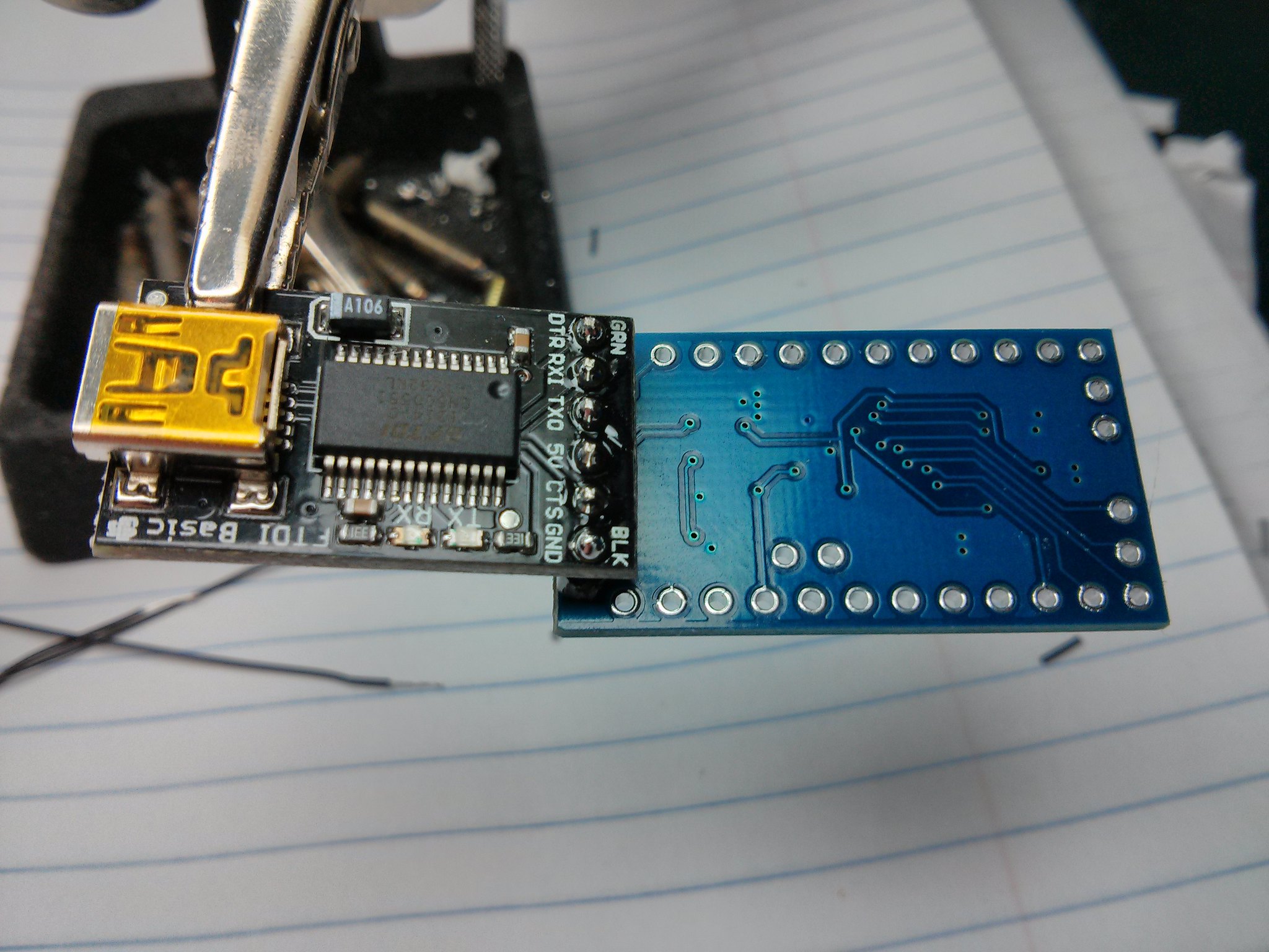
The FTDI Basic

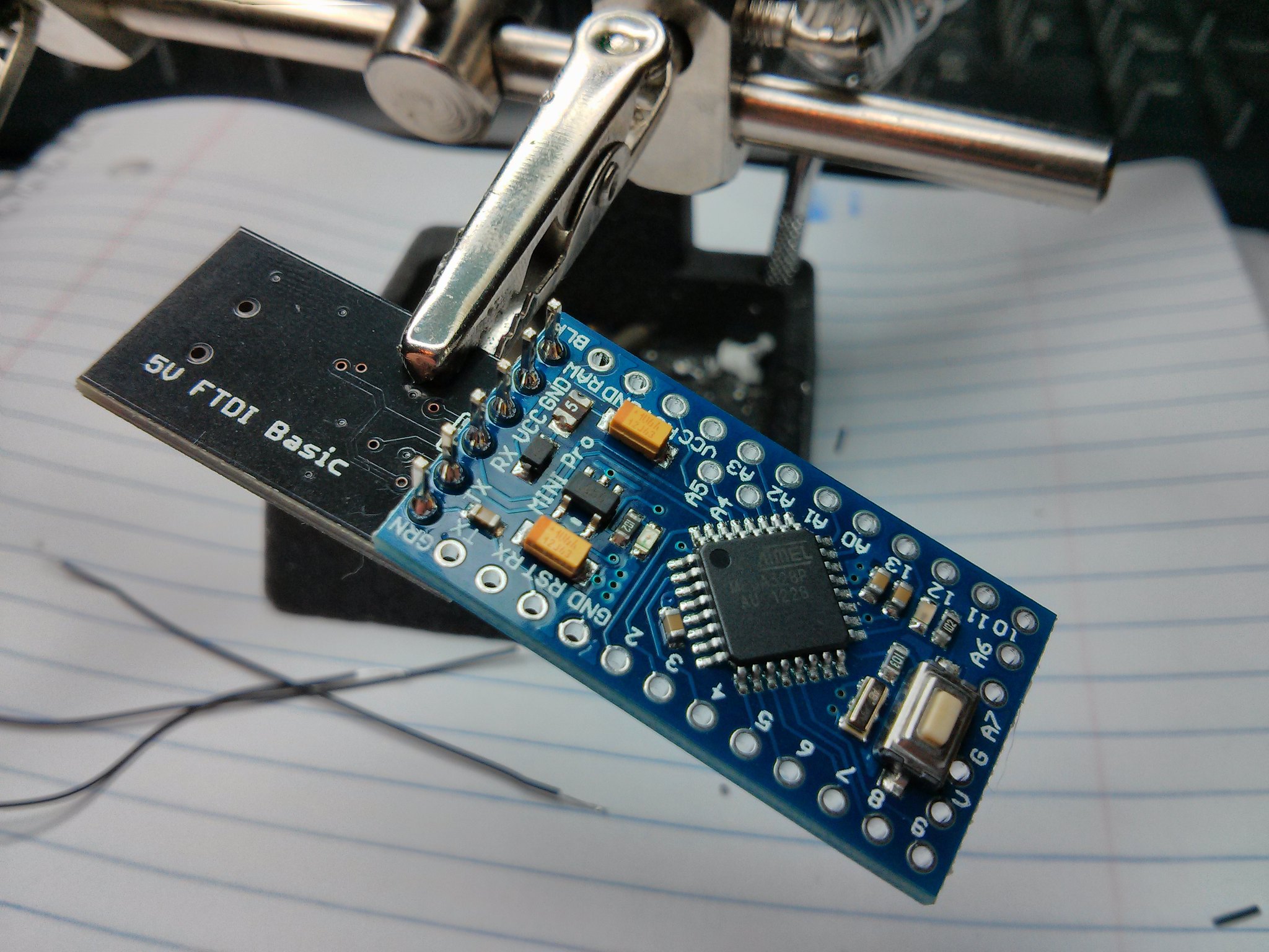
The Arduino Pro Mini

12ianma wrote:

line level won't power headphones from an SGB. you'll need to put it into an amp or powered mixer to hear it.


This.

I ran into the same problem trying to test SGB prosound directly to headphones resulting in nada nada

The prosound needs to be fed into an amplifier before it can be heard.

On a side note: Is anyone else's SGB prosound lacking significant audio signal from the right channel?
Or is it just mine hmm
Cause I've prosounded two SGBs but this seems unavoidable.

I've considered tracing the audio signal from the cpu to the heaphone jack in the original gameboy.
In theory putting the same kind of components in place to feed off of the SGB's cpu to make it so it doesn't have to be ran through an amplifier / an attempt to restore the right channel to what it is expected.

42

(5 replies, posted in Trading Post)

I am interested in your cart
What are you particularly looking for from trade?

43

(463 replies, posted in Nintendo Handhelds)

Teh D3th St4r wrote:

Anyone have a Gameboy with a busted screen they want to give me? I need another cartridge port.

I have a super gameboy and a few pocket's cartridge port I could part with.
If your interested PM me, also if you need any help troubleshooting I wouldn't mind give you my input on the matter.

44

(135 replies, posted in Nintendo Handhelds)

Boddah wrote:

Update: 2/20/13
The MMC is now installed and fully functional. The cart pass through also works great. I decided that it would be best to put a plate on the top side of the GB to cover all the openings, and to give it more support. I used the lid from an old project box and cut out a plate from it, I then mounted it with screw to the top of the DMG. With all of that out of the way I can start doing the final wiring on the back half of the DMG.

Congrats on MMC integration!
I might have to incorporate it into my current project if there isn't enough room for adruino and such.
Keep us posted your 90% of the way there

45

(135 replies, posted in Nintendo Handhelds)

Boddah wrote:

Alright so I checked the connections for the points in your pic, GoingHam. All of the yellow points are indeed still connected to the purple point. I also reinforced the connections to the power board, but I'm still getting the same thing....
I'm thinking the problem may be caused by the power switch. When removing the power switch and adding a new one, wouldn't you just need to connect the pins in the correct order on the switch? Would cutting down that corner cause any problems? I'm almost certain that I only cut the ground pad off of the top left corner so I can't figure out what would be causing the problem...
I think what I'll do is remove all of the parts (power board/switch, cap C1), remove all of the old caps, clean the board thoroughly, put the new caps in, and reconnect all of the parts then see if that helps. If anyone has any other suggestions please shoot them my way!

The switch should work when connected to correct order of pins. Cutting the board shouldn't be to much of a problem, you could try tracing back the leads to those 4 points for the power switch. I'd say reconfirm your presumed pin out of the stock power switch by using your multimeter on a currently working PCB. Its worth checking if attaching the old switch fixes it as that rules everything else out. Although the one horizontal line might be a clock problem I'm not entirely sure.

46

(135 replies, posted in Nintendo Handhelds)

I had a similar problem one time when cutting the area near the C1 capacitor.
Also the device is turning on so both lead me to believe its a issue with one of the following:

Firstly I'd check to make sure there is connection from the purple point to any given point in the areas marked in yellow
Secondly check the connection of your wires from the power board to the rear pcb
Thirdly if none of those remedy the situation, reattach the legs of the C1 capacitor to new locations

Any chance of major update on this build blog in the near future?

DogTag wrote:

Thank you GoingHam. Everything there makes sense, but still hasn't solved my problem.

I ended up doing the USB thing, and the keyboard does switch on, and at first I managed to make LSDJ say "I80" (I guess that the keyboard was somehow synced), but it wasn't working. Then, all of a sudden, it stopped displaying I80 and so I'm stuck.

I checked with my multimeter and with the male PS/2 connector that the connections were fine and so it seems! The only weird thing is that when I probed the "data" and "clock" wires of the keyboard on my oscilloscope, they were both in "high" state, and only went for the logic "down" when pressing keys, but both of them! I thought the clock would have a steady periodic "pulse" or something, and the "data" aperiodic signals when pressing keys... It's all weird.

What manufacturer of keyboard/ model# are you using?
The vast majority of ps/2 keyboards (atleast that I've run into) aren't LSDJ compatible.

Here's an old thread that might give some insight to your confusion.
http://chipmusic.org/forums/topic/6698/ … lp-please/
Here's an old thread that might give some insight to future confusion.
http://chipmusic.org/forums/topic/7615/ … ch-thread/

DogTag wrote:

Ok, I've broken a pin when trying to swap it, so:

I thought about vcc through USB. Will then the ground on the DMG have to be connected to the ground of the keyboard and the ground of the USB?

Couldn't you just try the pin swap again with the other half of the spliced DMG04 cable rather then bringing a usb in the mix?