Hello all.  I've written a little guide on how I modded my Gameboy for better sound.  I followed other guides that you can easily find here & on Google by searching for "Gameboy prosound".  There are plenty of guides around, but I did this anyway, for anyone who may want to see yet another example.  Here's how I did mine...

Open the case with a tri-wing screwdriver.
NOTE:  Some Gameboys have normal philips-head screws, so be sure to watch out for that.

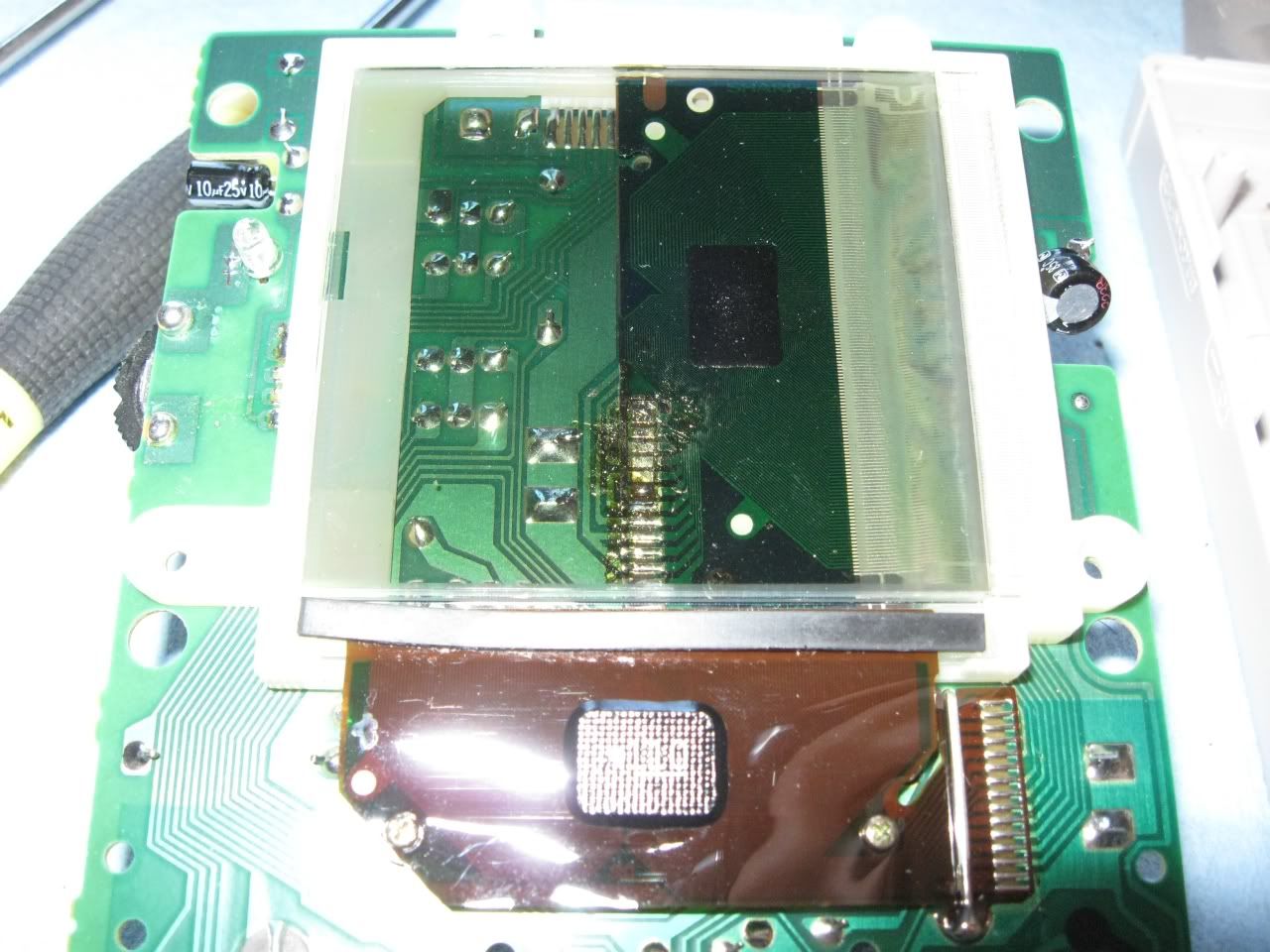
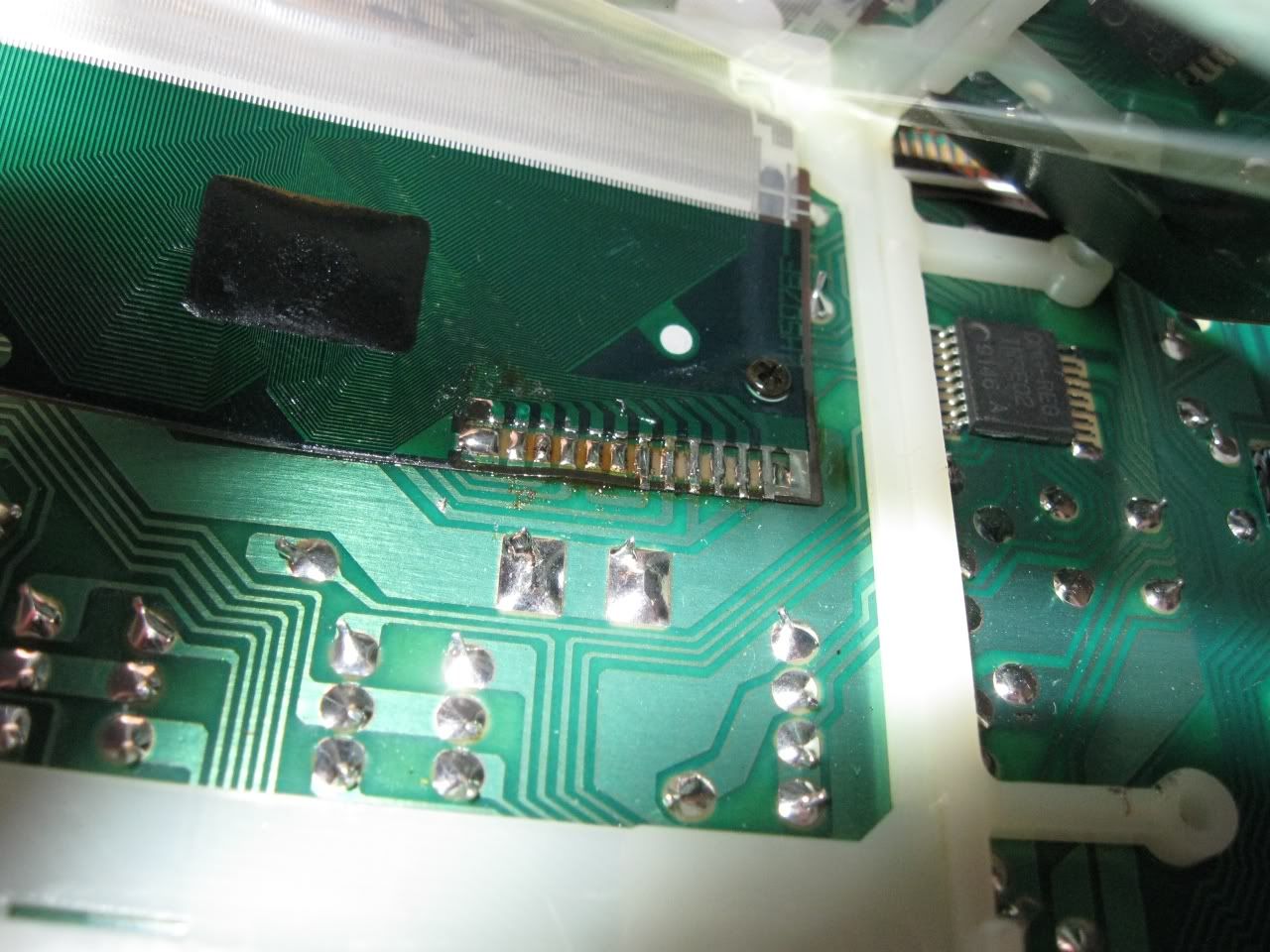
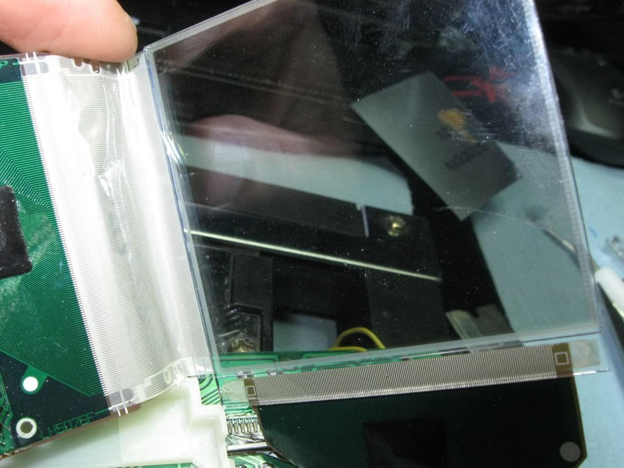
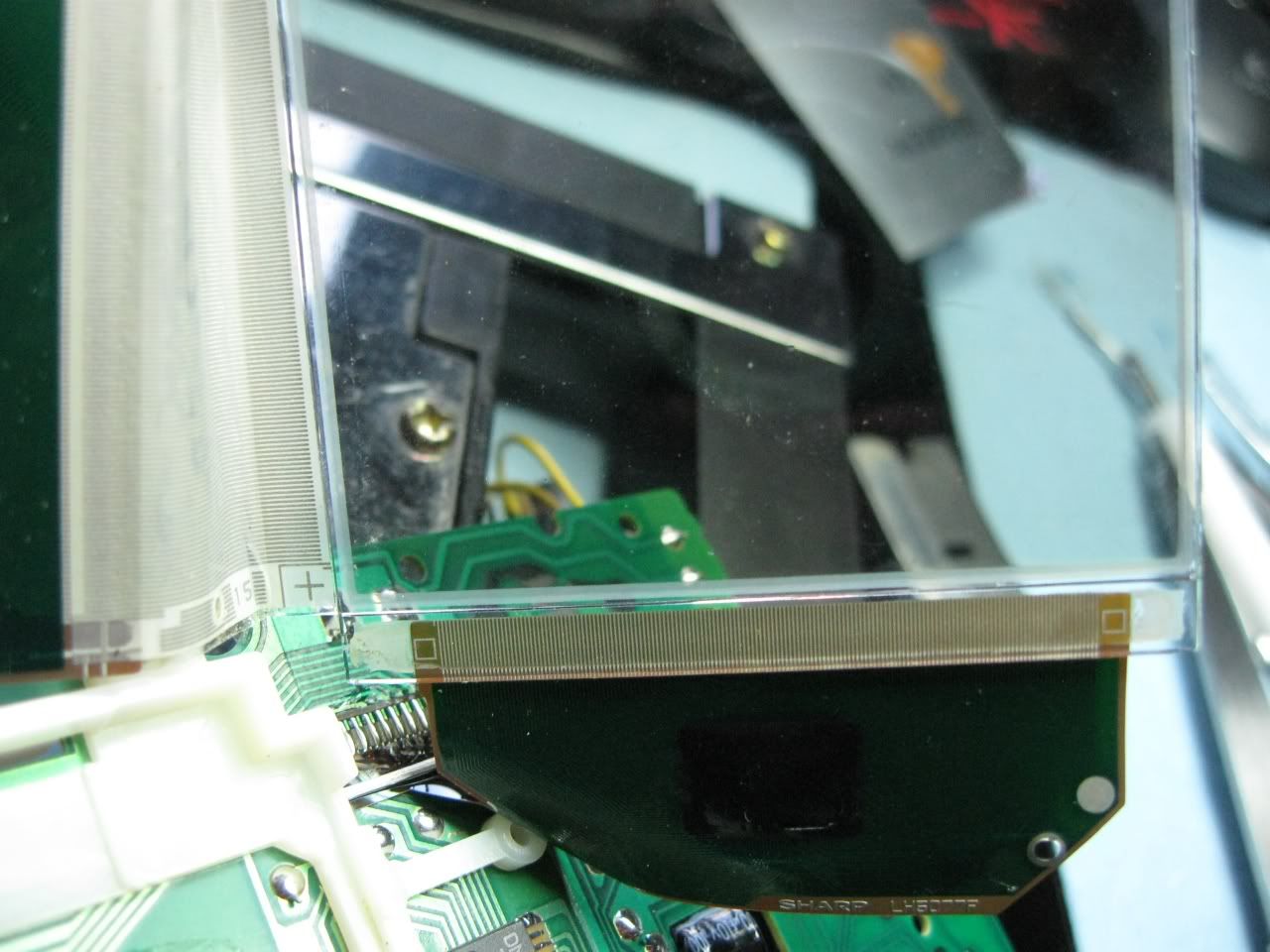
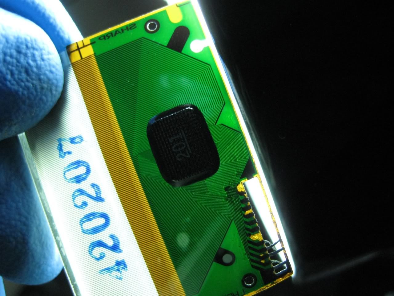
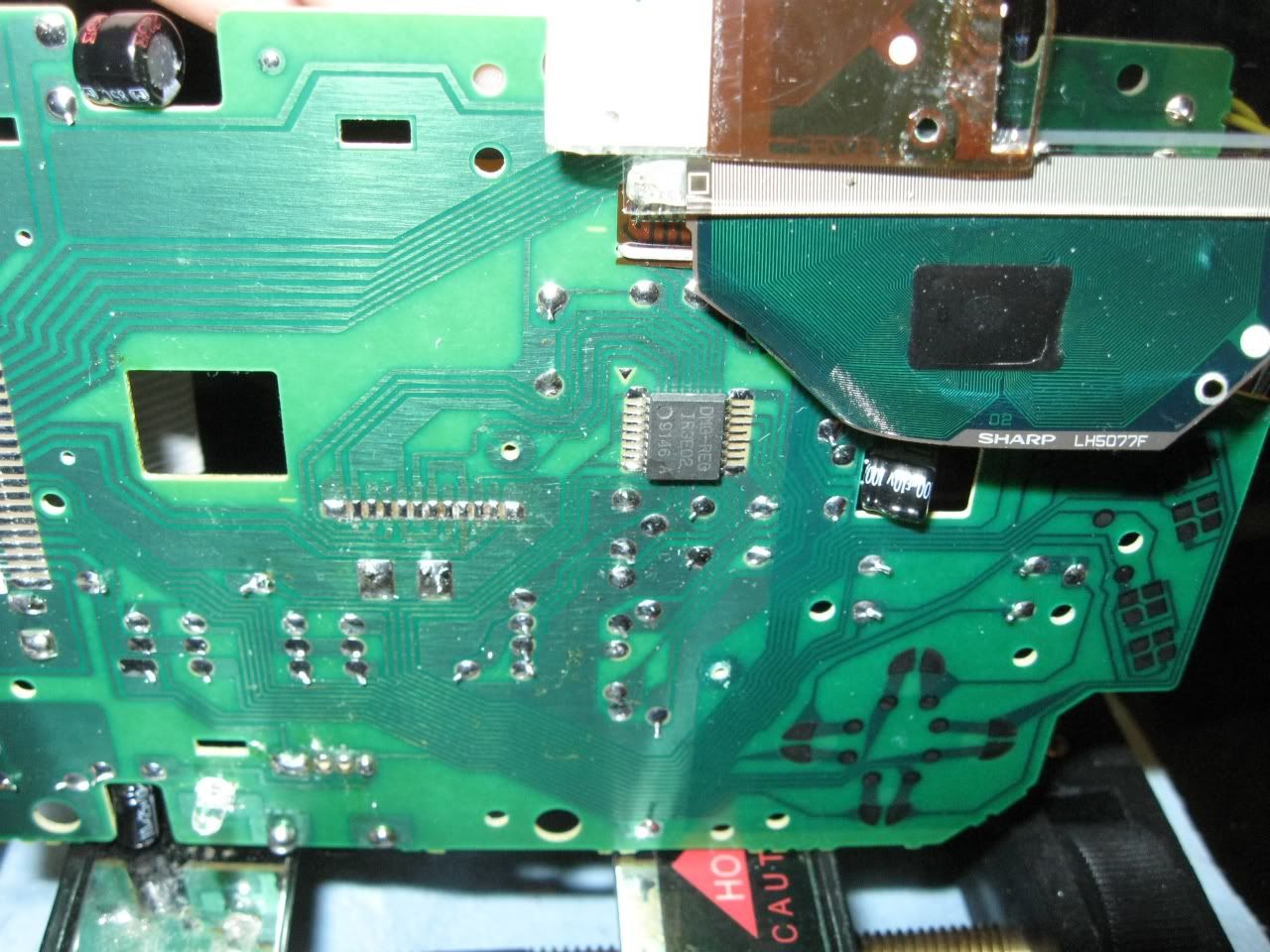
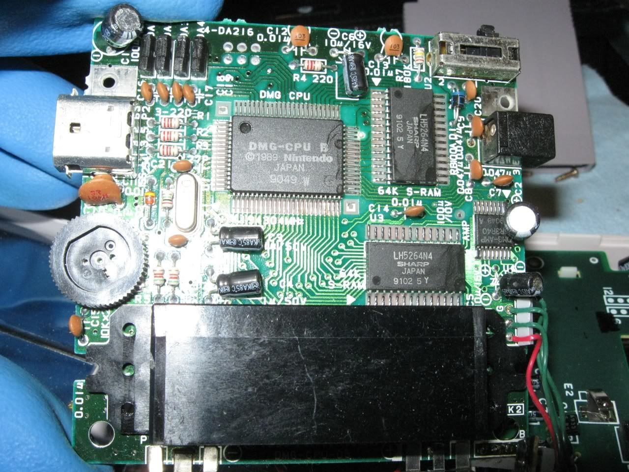
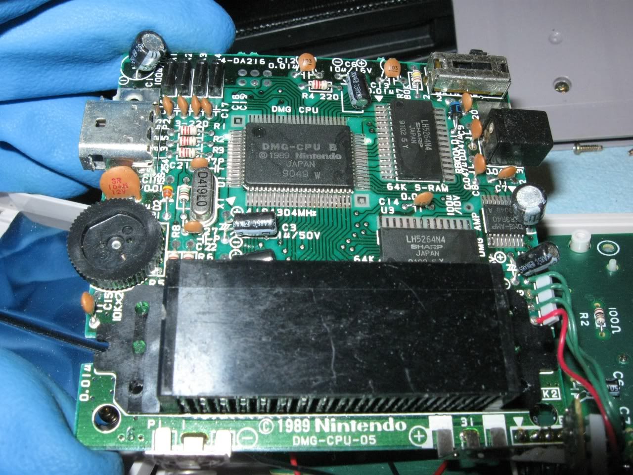
As you can see, this one already has a backlight.  That might make it slightly trickier to work with, but it's not too bad.

All apart.

The stereo jack will go in the front case, down in the left corner.

26AWG wire seems to be OK for this.

The stereo jack has its pins labeled.  '1' is for Left, '2' is for Right, & '3' is for Ground.

It's always good to use soldering flux while soldering.  This is a really good one to use.  "CHIPQUIK SMD291 No-Clean Paste Flux"  The paste flux not only protects the solder, but makes it easier to solder as well.

Flux...

& solder.

Line it up inside the case to see where you want to drill.

I use a spring loaded center punch to make a mark on the spot that I want to drill through.  This makes it easier when you first start drilling by giving the drill bit a hole to stay centered in.

Only the threaded part will stick out of the case, so use a drill bit that's slightly bigger than the threaded part.  1/4" looks like a perfect size to use.

Time to drill.  Use any smaller size drill bit to start off.  Having a small hole in place first will make it easier to use the big drill bit.

Now use the 1/4" drill bit.  This plastic is very easy to drill through.

Perfect.

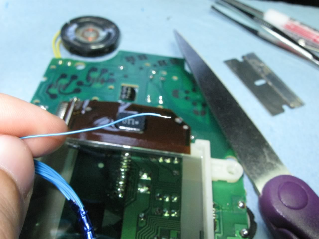
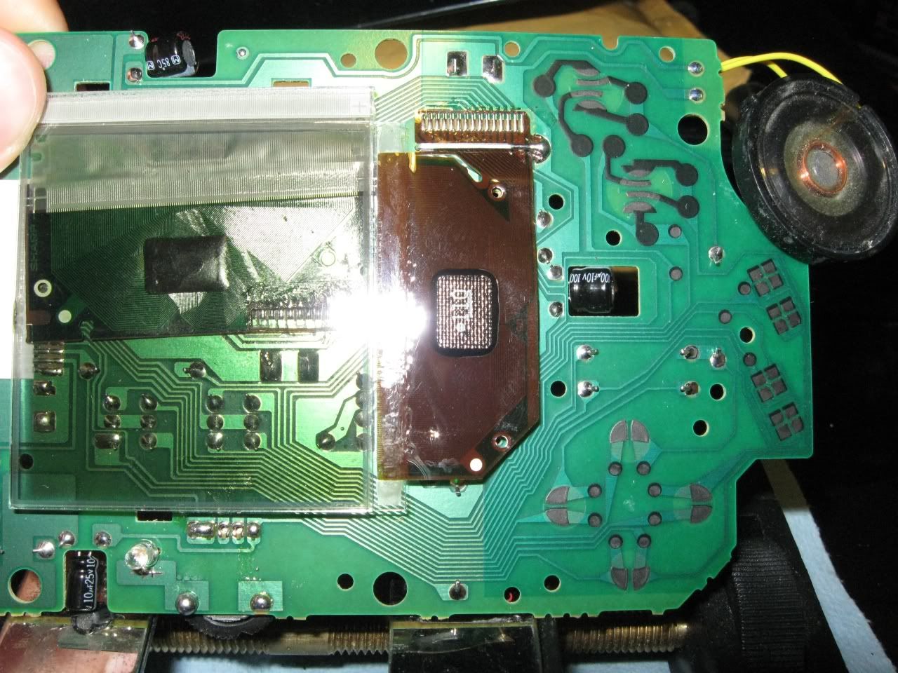
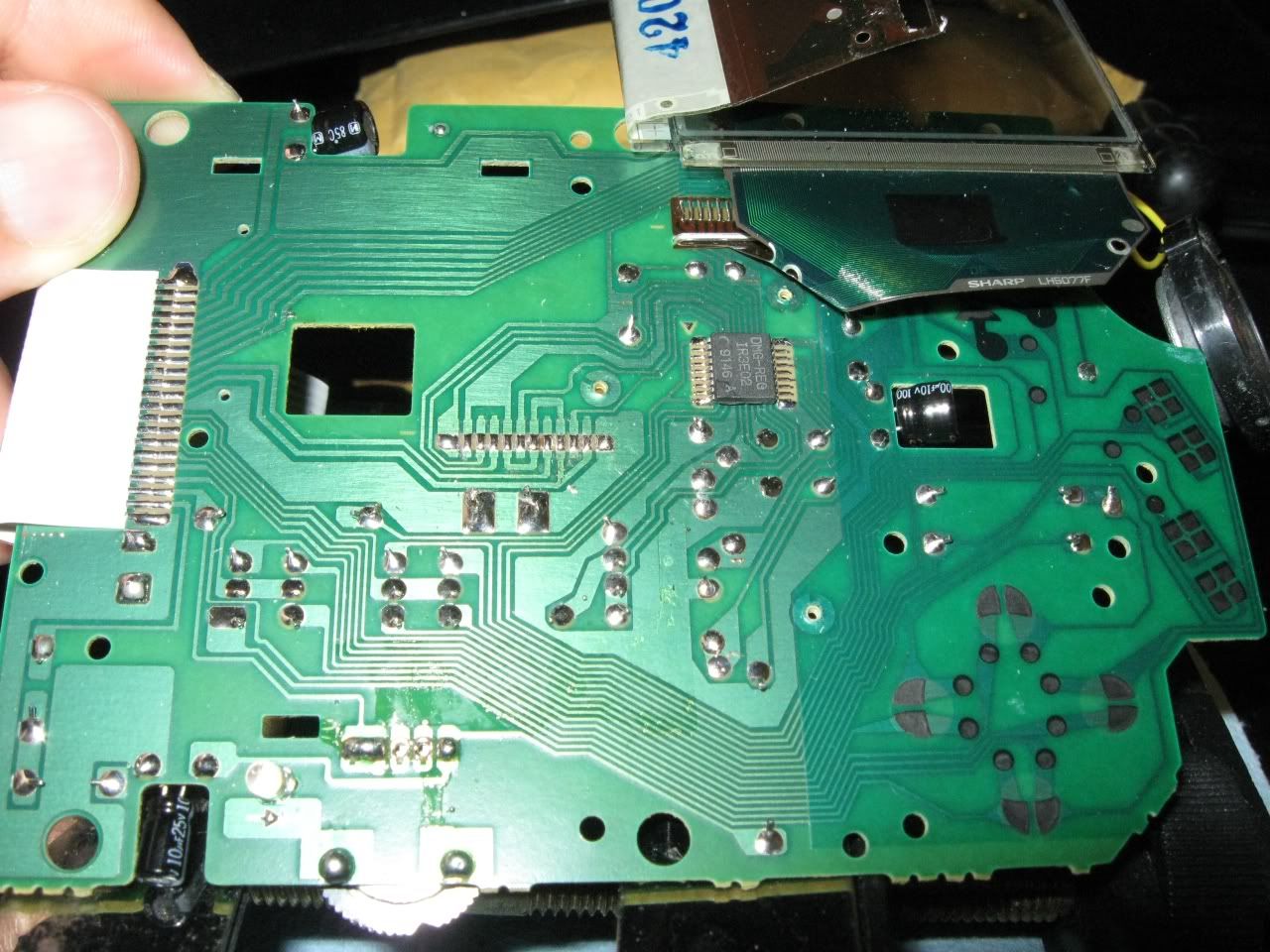
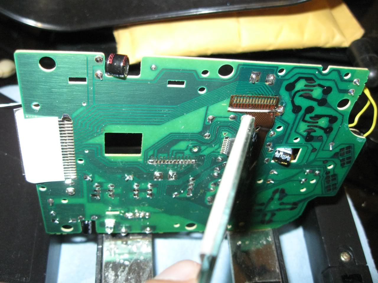
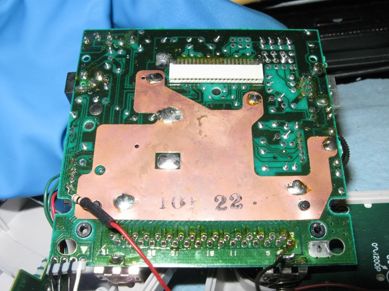
Now, on the bottom half, look at the headphone jack board.  There are 2 capacitors sticking out to the left.  They have to be bent underneath the board to make room for the stereo jack.

Carefully bend them back under the board like this...

& screw the board back into place.

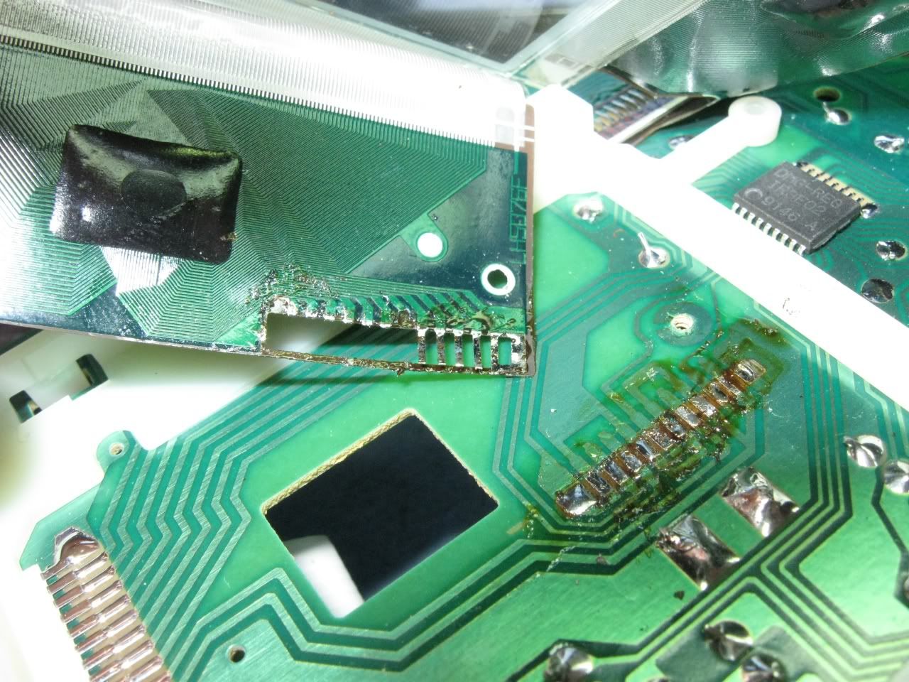
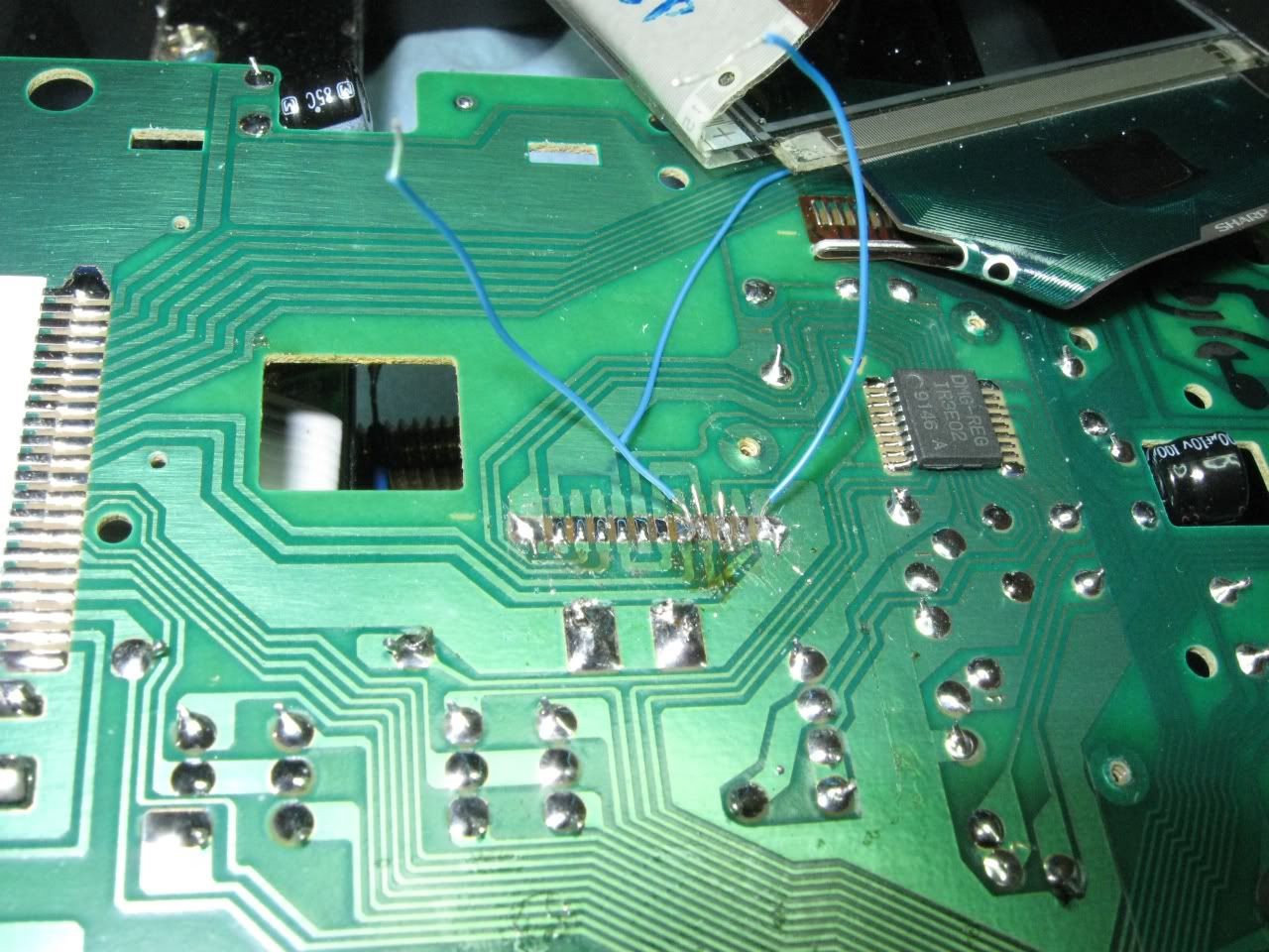
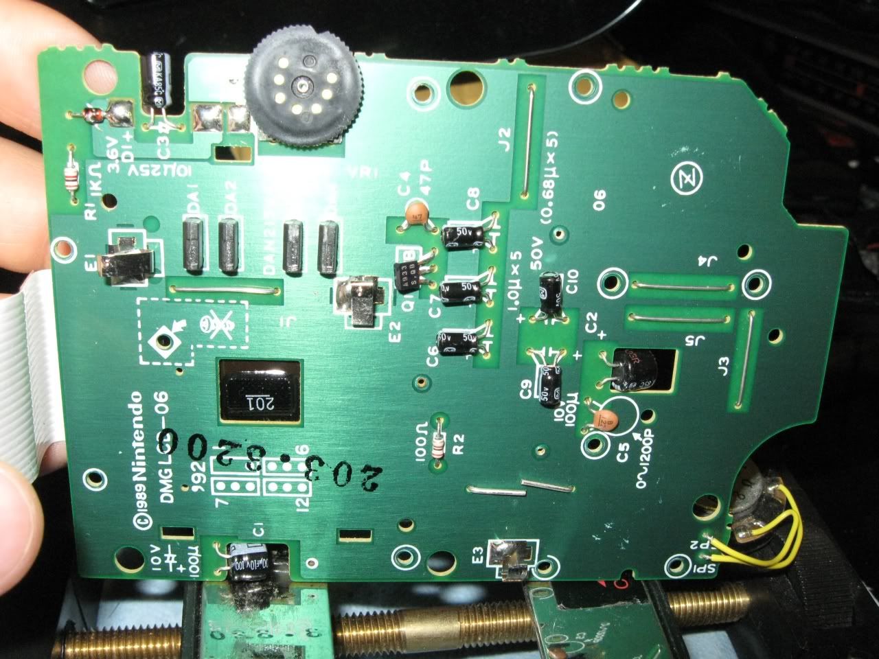
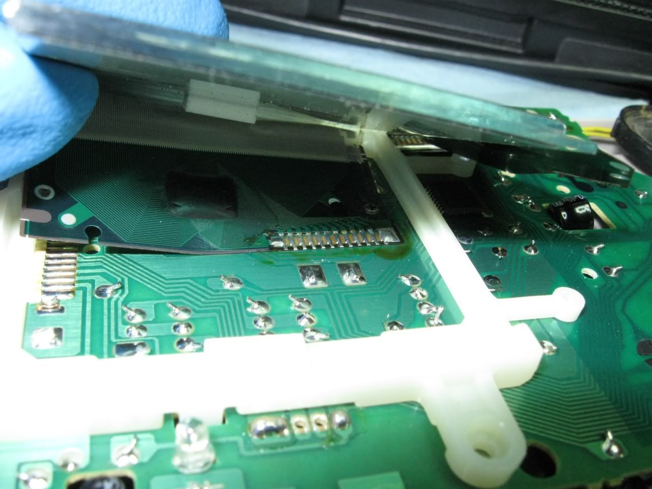
Now to solder the wires onto the volume potentiometer legs.  There are 5 legs soldered through the board.  Google search other people's guides, & you will see some pics that have them labeled.  Starting from the top, they are:
Right (before going through the potentiometer),
Left (before going through the potentiometer),
Left (after going through the potentiometer),
Right (after going through the potentiometer),
Ground.
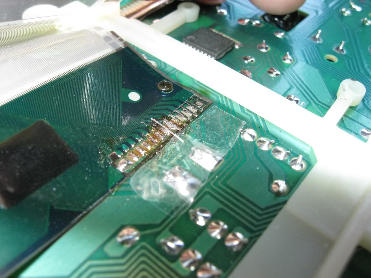
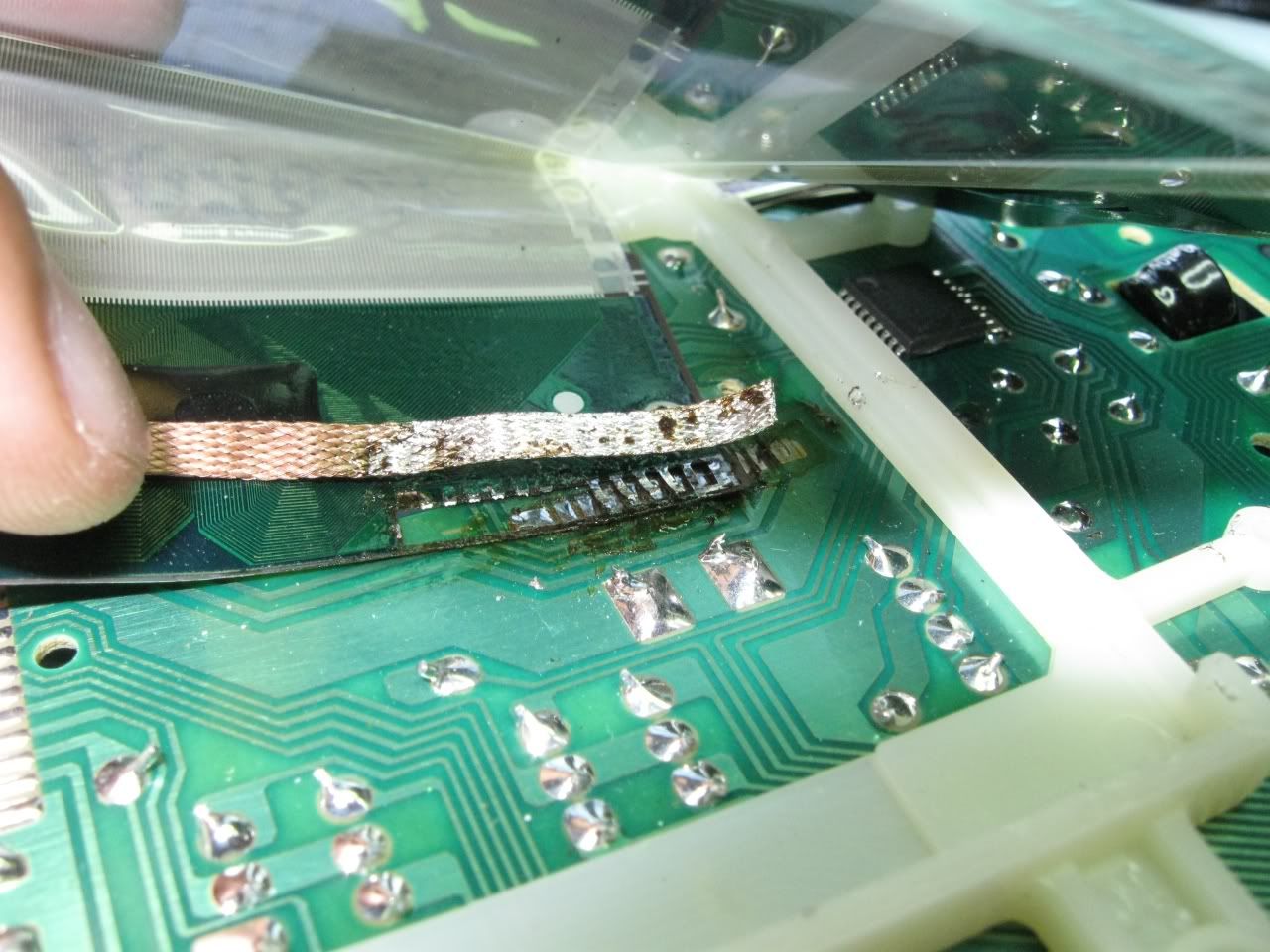
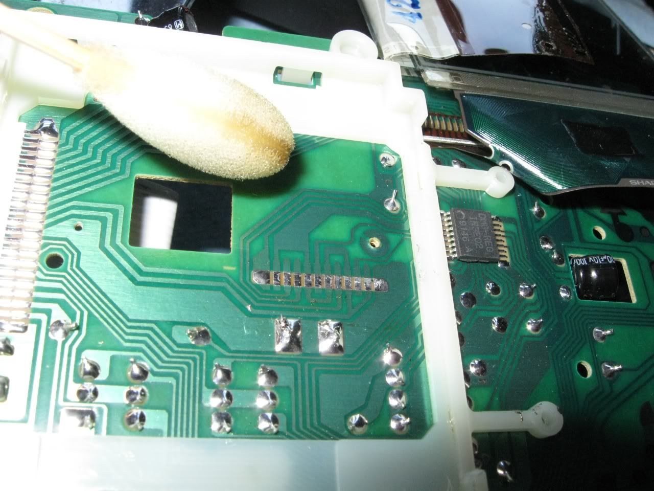
Clean with alcohol...

Flux...

Put a little solder onto the wires to make it easier...

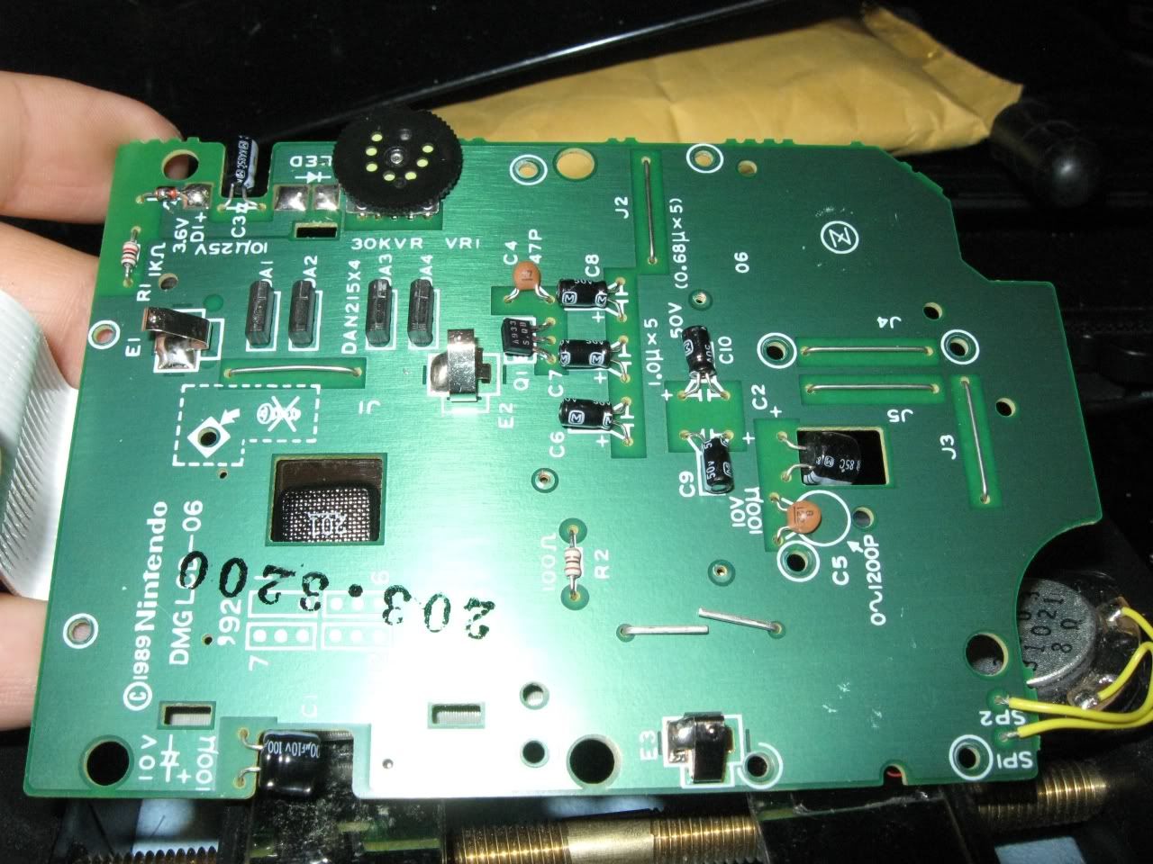
& solder them on.  Clean with alcohol afterwards.  I chose to solder onto the points after the sound goes through the potentiometer.  This way, I can control the volume in the stereo jack with the volume knob, just like the headphone jack.

Close-up.

Take a look at how I bundled the wires together with a little electric tape to keep them nice & neat.  Don't do that where they're still on the board.  I learned the hard way.  If you bundle them together while they're still on the board, they will get pinched & squeezed, & you won't be able to close the case all the way.  You can bundle them anywhere that's away from the board, like down below.  Routing the wires can be a little tricky.  This is something you'll have to spend some time with to make sure you get it right.  You have to make sure that you don't place the wires in a way that they'll get pinched by the case when you close it.  Take some time & test close the case a bunch of times to see where & how you can place the wires without pinching them.

Put the stereo jack in place & tighten the lock nut.

All done!!!

Now, time to close the case.  Again, don't bundle the wires on the board like I did here.  It won't close like that.  As long as they're on the board, the wires must be laying flat out, & not on top of each other.  Also, try not to let them get pinched in between the screw pegs as you close the case.

Finally, screw the case together, & your prosound mod is done.

All finished!!!  Enjoy your newly modded Gameboy!!!  big_smile big_smile big_smile

Ohai.  smile  It's been quite a long time since I've been on here.  I'm gonna try increasing my online presence a little more from now on, & what better way to do so then by sharing some knowlegeable stuff???  I've done a few things that will probably be useful to many people here.  So, without further ado, let's get started.

I made a guide on how I made an audio Y adapter with 3 stereo jacks.  They don't seem to sell something like this anywhere, so I had to make my own.  This is good if you need to listen to 2 sources with your headphones or something.

Let's begin.  The goal is to have a wire with 3 female headphone jacks & no plugs.  I used 2 headphone splitters for this.

First, I cut the 2 jacks off of one splitter, & then I cut one jack off of the 2nd splitter.  The rest of the 2nd splitter won't be needed, but it should still work as a small extension if I decide to use it for something.  For these Belkin splitters, they used 2 wires for Left & Right, & they used the shielding for Ground.

I decided to test just to make sure all wires are matching.  They do indeed match.  The way headphones are wired is like this: on the plug, the Tip is Left, the Ring directly underneath it is Right, & the Sleeve, or the bottom part, is Ground.  If you look inside the jack, you can see the 2 prongs that will contact the Tip & Ring for Left & Right, & the rest of the metal that you can see sticking out of the top is Ground.  By sticking a probe into the jack & touching the bottom contact that contacts the Tip of the plug, I checked for continuity, & can see that this runs on the red wire.  The next contact, for the Ring, runs on the white wire.  The gold strands are soldered to the Sleeve, & are used for the Ground.

After the soldering is done, you should use heat shrink to cover up the exposed wires & protect them from touching anything else.  However, you have to think ahead & put heat shrink on the wires BEFORE you do any soldering, because once you solder the wires together, you can't take them apart unless you cut them.  It's easy to forget to do this.  So before anything, be sure to put a big piece of heat shrink on the wires that will cover the whole assembly.  I put a 2nd small piece of heat shrink on the single wire just in case I needed more, but in the end, I didn't need it after all.

Since these wires are so small, working with them can be a little tricky.  First, I twisted the 2 red wires together on one side.  Then, I put some heat shrink on the other red wire, & I intertwined & twisted the 3rd red wire with the first 2 wires.  I put a little soldering flux on the wires (I use Chip Quik SMD291), & then I touch the soldering tip underneath the wires & melt solder on from the top of them.  They are very small, so this wasn't too hard to do.  Then, slide the heat shrink over, heat it up so it shrinks, & this is the end result.  Left is now complete.

Now, I do the same for the white wires.  I put some heat shrink on first.  However, now that the red wires are holding both sides together, I can't twist all 3 of them together.  That's OK.  As long as the wires are pushed together & the strands are intertwined, they can still be soldered together quite well.  Just make sure the strands are intertwined & squeezed together nice & tight, & try not to move them while soldering.  This was a bit tricky, as I had to brace them against something, hold them with one hand, & solder them from underneath in mid-air with the other hand.  Since they're so small, you don't really have to apply force with the soldering iron, so that helps.  Heat shrink, & now the Right side is done.

Now for the Ground.  When I started, I didn't quite realize that I would need more length, as the wires on both sides weren't quite overlapping too much.  I probably should have cut the red & white wires shorter on both sides so that the ground wires would overlap more.  I just kept on going anyway.  I intertwined the strands by pushing them together & squeezing them, then soldered them together.  It worked quite well.

That completes all 3.  Now, just slide the heat shrink over everything, heat it up to shrink it, and this is the final result.

It's not very pretty, but the goal has been achieved.  I really wish they would sell something like this.  Oh well.  Time to test!!!

My 2 sources with an extension wire for each...

And success!!!  I can hear both sources perfectly & clearly at the same time.  On each one of them, Left goes to Left, & Right goes to Right, just as it should.  This job is finished, & is a total success!!!  big_smile big_smile big_smile

Hey, I just discovered that you can export an entire 16 block section as a sample, & then load that sample & play it back with 1 single note.  See if the Gameboy version has an option like that too.  That would make it easier.

Hey.  Don't know if you care to hear from a beginner, but I'll chime in anyway.  I see nothing bad with your song.  It's really cool.  I like the way you were able to keep a certain mood throughout the entire song.  I think that's important, & something I'm struggling with in my own practices.

About the arps you made, you say you used delay on every other note for that???  I have Nanoloop on Android, & I tried making arps...  The only way I could figure out how to do it was by filling an entire 16 block section.  I would write 4 notes, then write them again with a little less volume, then write them again with a little less volume, doing that 4 times.  It wastes an entire 16 block section, but I don't really know an easier way to get it done.  But the way you did it sounds pretty good.  Then again, I think Nanoloop on Android may be very different from & much more limited than the one on Gameboy, I think...

Well anyway, really nice track.  You're off to a great start with the chiptunes.  ^_^

Edit: I just noticed your site & your other songs.  Pretty cool stuff.  Do you find it harder working with these chiptune programs & hardware that are more limited???

85

(17 replies, posted in Nintendo Handhelds)

This does not sound like a battery issue.  Before you try for a return, try these things:

-Reformat the cartridge.  Reformat it a couple of times.  Do this to both the A side & the B side of the cartridge.  Then flash LSDj back onto it & try it.

-Use a different USB cable.  It's possible one of the prongs in the cable is not making a strong contact.  If that's the case, it can lose connection & quickly reconnect before you even notice.  If it does that while you're writing to the cartridge, then whatever you're writing WILL be corrupted & cause exactly the type of problems you're describing.  Also, to be safe, plug the cable in tight & DON'T TOUCH IT, especially while it's writing.  Place the cartridge down & do your flashing.

-Finally, check the Gameboy itself.  Please do keep in mind how old these things are.  The contacts where the cartridge plugs in may be dirty.  See if you can stick a Q-tip doused with isopropyl alcohol down into that contact area in the Gameboy.  Try to clean the contacts.  Isopropyl alcohol is used to clean electronics, so you don't have to worry about moisture damage or anything like that.  Try anyway you can to rub those contacts with alcohol.  Make sure you blow it dry before connecting & turning on.  Alcohol evaporates very fast.

Hope this helps.  Good luck.

86

(7 replies, posted in Nintendo Handhelds)

Sometimes, the lines won't go away no matter what.  Try this: if you have a heat gun, make some kind of small nozzle for the air to go through, maybe using aluminum foil wrapped into a funnel???  Try to focus the hot air into a small area, that way you can concentrate on the area that needs to be worked on.  Also, work on that cable up right by the screen, & down away from the screen as well, moving back & forth.  You may get lucky.  I've found hot air to do this much better than a soldering iron.

87

(10 replies, posted in Releases)

Awesome song!!!  I would've never imagined this was done with DS-10.  Nice work.  big_smile

egr wrote:
kitsch wrote:

this would actually be more suitable for my needs in the long run as well

Indeed.  I've got several Android devices but nothing Apple at all.

Looks nice.  An android version would be really nice too.  big_smile

nitro2k01 wrote:

You might be able to scrape off the soldermask (the green layer) and solder directly onto the connector. Though, that's probably destined to fail. What you might want to try instead is to transplant a Gameboy Pocket display onto the display board. This would still involve fine soldering, but at least you'd be soldering on surfaces meant to be connectors.

Hmmmm, a Gameboy Pocket LCD eh???  I just took a quick look on Google & already found some interesting information on that.  Thanks for pointing me in that direction bro.  I'm all for hardware hacking, & if I can find a way to re-engineer this screen setup, I'll gladly do it & document it.  I'll start researching once I get a little more time.  I'm keeping this unit for experimentation.  Hopefully, something good will come of it.

OK, I just wanted to throw a bit of info out there.  This concerns the method of repairing the missing lines on the Gameboy screen, which I'm sure most of you know very well.  In my experience, I have found that the soldering iron trick does NOT work all the time.  After doing that on a few DMG-01s, only 1 got fixed & stayed fixed.  The others would not stay fixed at all.

However, I recently came back to one & tried my hot air rework station with a small nozzle & low pressure.  Hot air fixed the lines very easily, & they stayed fixed, even when I press on the cable.  What the soldering iron couldn't do, hot air did much better, & much easier too.  It seems that hot air works much better than a soldering iron.  I used around 300degC.  Of course, not everyone has a hot air rework station... you could use a heat gun, or even a hair dryer to heat the ribbon where the lines need to be fixed.  If anything, maybe block the air from blowing on the LCD itself too much.

Anyway, I recommend using hot air instead of a soldering iron to fix the lines.

Hello all.  OK, so in my attempt to get another DMG-01 up & running, I ended up ripping off a couple of the connections on the ribbon cable behind the screen.  Long story short, in the end, I ended up taking the whole thing off, so that Gameboy's toast.  Damn Nintendo & damn Sharp for making this little screen such a proprietary setup.

Seeing how impossible that ribbon cable is to work with, I attempted to solder some wires from the pads to the ribbon cable.  However, soldering onto a ribbon cable proved too frustrating for me, even after scratching off the coating to expose the traces.  I gave up.  So I made sure to take some detailed, close up pictures of the motherboard, traces, & everything that's behind the screen.

I hope these can be useful to somebody who wants to plan & experiment without destroying theirs first, or something.  Or even just to document.  Feel free to take these pics & use them as you need.  You can get bigger versions on my photobucket page.  Each picture shows the link.  It would be nice if someone could come up with a different way to connect this little screen... I hate the way they set it up.


FRONT MOTHERBOARD


This is what a good one looks like.  If you're backlighting your DMG-01, please do be careful not to bend this ribbon cable too much, or you will suffer like me.  hmm


REAR MOTHERBOARD

Hi all.  I guess I'll do this again...

I'm from NYC & I'm just getting into the whole chiptune scene.  Though I never have time in my life for anything right now, I'm doing my best to be a part of it all anyway.  I'm learning how to use LSDj & loving it.  I'm also using Nanoloop for Android.  Having a good learning experience with both.

I love anime & video games, & especially the music.  I'm also a huge vocaloid fan.  Maybe one day I can do chiptune / vocaloid music.  Well, I'll be lurking in the shadows for quite some time cause I never have time for anything, but I'll pop up every now & then.  Who knows... you may even see a "mysterious" song suddenly pop up from me one day.  : )

Well, that's all for now.

93

(126 replies, posted in General Discussion)

Count me in.  I'll definitely be there.

Hello everyone.  For my 1st post here, I'll join in on this one...

I'm over 30 now  o.O , & am currently a diesel truck mechanic.  I hate doing that dirty work though.  I'm working on starting my own business refurbishing & selling smartphones online so that I can support myself & not have to work my life away for some company.  I got myself into immense debt many years ago, mostly from cars & car stuff, & now I never have time in my life for anything.  I'm working very hard to change that.  I'm on my way to paying off all my debts so that I may have a 2nd chance at life.  Being over your head in debt is like modern day slavery.  You can't live a life, or do anything.

Aside from all that, I'm an aspiring artist/musician, & a big nerd.  I love anime & video games, & especially music from video games.  I love the fact that people are making music now with the video game systems we grew up with.  : )  Art & music is what I love the most.  Once I free my life, I definitely want to put more time & effort into music.  Even though I hardly have any time in my life for anything right now, I'm still trying to get myself into all of this anyway.  I just got LSDJ up & running, & I'm practicing & learning it every day on the subway trains.  Being on the trains is the only time that I actually have time for it.  I'm slowly learning it, & I love it so much.  I have no experience in making music whatsoever, but I'm gonna try my best with this.  I love it so much.  Well, enough rambling.  I have to try & get my 2 1/2 hours of sleep now.  o.O

That's all for now.  And hello to everyone!!!  Glad to be here.  : )