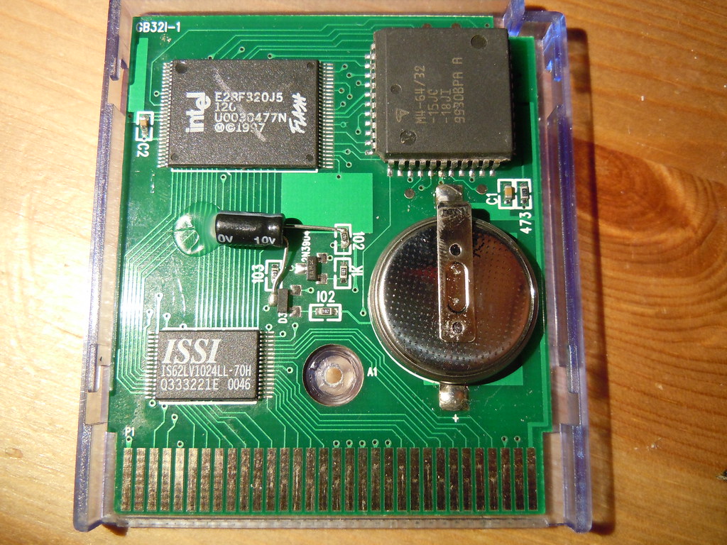
Re: canopy type battery holder. I don't see this as feasible. You are relying on the PCB layout to provide the cathode (negative battery terminal) connection. On the yellow cartridge, the cathode is to the left of the battery. You could perhaps solve this by adding a little bit of wire soldered to the pad which goes under the battery, but I don't think you can guarantee good contact this way. You also need to attach the other  side of the "canopy" for mechanical stability. This is farily easy to do if you scrape off some of the solder mask from the ground plane above the battery, and also disconnect said section of the ground plane from the rest of the ground. (Just a few cuts with a knife.)

However, that seems a bit hackish, and might create problems with data loss because the connectioncomes loose. The way I would probably solve this is with a 180° tabbed battery. Solder the anode (positive battery terminal) to the right place. Bend the other tab and fold it around the top edge of the PCB. Solder a jumper wire between the tab and the ground pad on the board. This would require some thought when bending the tab, but should otherwise be the best solution.
...
Though again, thinking about it. that might not work because the top piece of the cartridge will occupy that space momentarily when you slide the cartridge shut.

Anyway, I think I would recommend a tabbed battery which is soldered into place rather than the canopy version, for mechanical stability reasons. This should still extend their life by ~10 years, so it shouldn't be that bad.

Oh and of course, maybe I don't even need to add that I would be interested in playing with these cartridges hands-on for some research. (Such as figuring out how to back them up and flashing new software to them.)

786

(10 replies, posted in General Discussion)

Closerized!

787

(26 replies, posted in Nintendo Handhelds)

I wonder how much of the noise that is picked up is EMI, and how much is fluctuations in the supply voltage. I wonder if a choke coil/LC filter on the voltage supply to the EL film would make any difference.

Somebody reported this long ago. I really should make a single page for LittleFM so there only one place to keep the links up to date.
Updated version: http://blog.gg8.se/gameboyprojects/week … apon02.zip

I have never touched this type of cartridge before. I do not know exactly what can or can't flash this cartridge. Maybe a bleepbloop/smartboy type flasher can flash it, maybe not. I'm working on a flasher of my own however, and would love to get my hands on this and see if I can add support for it.

It's using the FTDI driver which is pretty standard and available for all platforms. The problem is making the flasher software work. It's known to work perfectly on Windows (32 and 64 bit alike since there are no drvier issues.) For other other OS's ymmv. There's a port for OSX which used to work well, but I've heard reports it doesn't work. For Linux you'd have to build from source. At least the source code is available, so that's good.

Driver: http://www.ftdichip.com/Drivers/VCP.htm
Software: http://sourceforge.net/projects/gbcf/files/gbcflsh/1.1/ (Windows/source)
Mac links: http://thretris.blogspot.se/2009/12/gam … c-osx.html
http://randombazz.blogspot.se/2011/08/g … c-osx.html

791

(4 replies, posted in Commodore Computers)

The domain has expired but the website is still up. You can still access the forum if you add the fllowing to your host file: Don't assume it will be around forever, though. hmm

87.79.93.35 mssiah-forum.com

Instructions:
http://www.howtogeek.com/howto/27350/be … osts-file/

This is a bit like if a hardware store (you know, the type that sells hammers and screwdrivers) called itself Pro Tools. Confusion could arise, but meh.

Moved to the handhelds forum.

I know nothing about that game, but as linked above, I have experimented with this technique. Nintendo were right in not allowing it, as doing this on a GBC and above looks like a proper flickering mess. The LCD is fast enough to respond to change each frame, meaning that instead of seeing the average of the two shades you're aswitching between, you now see a 30 Hz flicker.

However, Nintendo may have had more immediate concerns, namely with the Super Gameboy. First off switching colors on each frame on a CRT TV gives you annoying flicker, just like on a fast LCD.
Moreover, the SGB works by copying data generated by a Gameboy CPU in the cartridge, into SNES video RAM. However, as far as I'm aware, the SNES and GB CPUs are not running in sync. Instead, I believe the data is double or triple buffered, so one buffer is displayed while another one is being filled up.

However, the almost 60 Hz generated by the GB CPU might not always line up with the almost 60 Hz. So every once in a while, a frame might be skipped or duplicated. Instead of getting an even flicker, you get flashes of darker or lighter color when the same pixel is drawn with the same color for two frames in a row.

Even worse, is what (I believe) happens on a PAL SGB, where the SNES side of things generates video at 50 Hz and the GB side of things still at ~60 Hz. Now duplication of blinking frames will happen all the time you will get a truly flickering mess.
If anyone is able to try my gradient ROM in the post linked above on a PAL SGB, please do so and report exactly how much of a flickering mess it becomes.


This is what one variety of the newer EMS cart looks like. It has an Intel chip in the top left corner. What I'm looking for instead has 4 smaller chips marked with the text Atmel and/or the Atmel logo. A cart bought
in 2008 is most likely the newer variant with an Intel chip, so yeah...

Find someone who can flash the cartridge and get an LSDj ROM patched with LittleFM, which lets you transfer the sav data over a link cable. Makes a world of difference.
However if this happens to be the older type EMS cartridge which has 4 Atmel chips (unlikely) I'm interested in it for my own use.

Yeah, that's what reminded me of this function. Though, this function could be abused by more "real" spammers which would also not leave much a trace on the server, compared private messages. It's not only that it might be annoying to users to get spam addressed as being by "chipmusic.org mailer", but if such a spam attack happens and a lot of people mark these e-mails as spam, this could also affect other forum e-mail like signup nd thread notifications e-mails.
So I figured it was a good idea to turn it off by default.

In the interest of preventing spam, the function that allows users to send e-mail to other users is now disabled for all users. Users who wish to be able to receive e-mail from other forum members can still enable this function by going to profile in the top menu, then settings, select "Hide your e-mail address but allow e-mail via the forum." and update profile to save the setting.

This function is different from private messages, which are not affected by this change and work just like before.

jefftheworld wrote:

Current (noted as I) is equal to Voltage divided by resistance.

I = V/R; V = I*R

That's how voltage works!

Well, yes and no. That's true for a purely resistive load, but in many situations and circuits, a too high voltage can be harmful (for batteries), or even a too low voltage (for switching power supplies.)

Where do you get the 125 V figure from?

Edit: The cable is just a cable. The voltage printed on it is the maximum voltage it's rated for, apart from that it will just carry the voltage from wall socket. There's nothing magic in it that will make it output 125 V if connected to a 120 V socket.